
How to Design Hydraulic Core Pulls: Sequence, Force and Angle Pins
Table of Contents
A four-cavity automotive connector tool ran 40,000 clean cycles before a hydraulic core pull started arriving 40 milliseconds late. The machine did not wait for the confirmation sensor, the next clamp stroke caught the slide, and the angle pin sheared two M10 socket head caps while the core buried itself in the cavity block. The repair took eleven days, more than the cylinders cost. Powered side actions fail quietly, then expensively, and the costly failures trace back to four design shortcuts: an undersized cylinder, no side-lock timing, no sensor interlock, or a seal package never rated for the resin and the heat.
A hydraulic core pull replaces a passive cam with a ram: an actuator mounted on or beside the mold withdraws the slide or angle core while the mold is open, then a reset path returns it. That is stroke independence It buys pull force that does not depend on clamp tonnage, and the ability to sequence several actions in a defined order. It also adds a system with its own failure modes, removed before the tool is cut by the work below.
This guide covers actuator-level decisions: when powered pulls beat slides and lifters, how to size the bore against pull force at a 140 bar system pressure, how angle pin wedges multiply force and generate side load, how to sequence actuation and cam-out with timing valves and low-pressure clamping interlocks, and how seals, bearings and hard stops decide whether the core repeats at 0.01 mm. Passive selection is covered in the lifter vs slide comparison and the general architecture in the side action design guide. All figures are typical published or industry values and must be checked against the machine, the resin and the tool drawing before release.
The Snapshot
- Pull force sized at 140 bar with a 20 to 30 percent margin. A 63 mm bore develops 43.6 kN theoretical at 140 bar; after friction the usable figure is near 39 kN, so demand 31 kN or less from that cylinder.
- Angle pins multiply force and side load in the same ratio. A 20 degree pin converts vertical force to horizontal thrust at roughly 2.75 to 1 ideal, and the wedge face sees a normal load of vertical force divided by the sine of the angle.
- Sequence confirmation in 0.2 to 0.5 seconds. The clamp command must be interlocked to end-of-stroke sensors on every pull, with low-pressure clamping armed as the last mechanical barrier against a crushed slide.
- End-of-stroke repeatability at +/-0.01 mm. Achieved with hardened stop blocks and close-cushioned strokes, not with flow control valves alone.
When a Powered Core Pull Beats a Slide or Lifter
A passive slide is elegant because it carries no hardware: a drive pin turns mold motion into horizontal travel at the cost of cam pressure and shoe friction. It stays the default for simple features. The economics flip in four situations, and each one has a number attached.
The first is stroke demand. A passive slide needs cam travel equal to the core withdrawal distance, and mold opening is finite. When the required pull exceeds roughly 50 to 60 percent of available mold stroke, the slide has nowhere to go and a hydraulic pull takes over. A 150 mm withdrawal in a mold that opens 120 mm needs an actuator.
The second is core length and surface drag. Long slender cores, over about 5 times diameter, grip the molded part. Pulling a 6 mm diameter, 35 mm long core out of a shallow-gloss polycarbonate housing can take more force than a small cam face can supply without marred parts, while a hydraulic cylinder aligns its pull with the core axis instead of a compromise wedge angle.
The third is timing independence. A passive slide moves whenever the mold moves, fine for one feature and a problem for three. When two cores must release the part and a third must wait for the stripper, only sequenced hydraulics honors the order.

The fourth is multi-axis work: an actuated core that must withdraw, then rotate, or two pulls in opposing directions that must never collide. For all four cases the powered pull costs 2,000 to 6,000 USD per axis installed, plus the plumbing, and saves the tool from geometry that would otherwise be unmoldable. The force numbers that set the boundary appear in the sizing table two sections below.
Undercut Geometry and the Stroke Envelope
The stroke envelope is fixed by three measurements. First, the pull distance: undercut depth plus 10 to 15 mm of clearance so the core face fully clears the part. Second, the interference check: the retracted core must clear every neighboring core, sprue bush and hot runner drop by at least 5 mm in all axes, including at temperature. A steel block at 170 degrees C has grown 0.5 to 1.5 mm on a 500 mm plate, and a cold interference check can lie by exactly that much.
Third, the withdrawal must be a straight line normal to the undercut faces. If the undercut angles 10 degrees off the parting plane, either the core rides an angled slide or the cylinder is mounted at that same 10 degrees. Mounting the cylinder straight while pulling an angled core bends the rod and opens the seal extrusion gap, and the failure shows 20,000 cycles later as weeping at the gland.
The envelope is also where mold bases and component standards matter. A pull sits in a pocket in the clamp plate or a sub-plate, with 25 to 40 mm of depth around the cylinder body and space for the fitting stack on the port side. If tie-bar clearance is below 400 mm, the plumbing exits toward the fixed side, and hose routing radius for 1/2 inch high-pressure line is 65 mm minimum. Those dimensions belong on the layout drawing, not on the assembler's judgment.
Cylinder Sizing: Bore, Stroke and Force Margin
Cylinder force is piston area times system pressure. At a 140 bar supply, which is 14 MPa, the common metric bore sizes produce the numbers in the table below. The theoretical column ignores friction; the realistic column deducts 8 to 12 percent for seal drag and rod packing on a clean, warm system, and the last column applies the 20 to 30 percent safety margin that the demand load must sit under.
| Bore (mm) | Area (sq mm) | Force at 140 bar (kN) | After friction (kN) | Max demand at 25 percent margin (kN) |
|---|---|---|---|---|
| 32 | 804 | 11.3 | 10.1 | 8.0 |
| 40 | 1257 | 17.6 | 15.8 | 12.6 |
| 50 | 1963 | 27.5 | 24.7 | 19.8 |
| 63 | 3117 | 43.6 | 39.3 | 31.4 |
| 80 | 5027 | 70.4 | 63.3 | 50.6 |
| 100 | 7854 | 110.0 | 99.0 | 79.2 |
← swipe to scroll →
Table note: forces assume 140 bar working pressure on the pull side and an 8 to 12 percent seal friction deduction. Confirm against the power unit relief setting and measured supply pressure at the mold, which commonly sags 5 to 10 bar under simultaneous multi-cylinder demand.
The demand load is three terms added together. Core friction is the core surface area times shrinkage grip times sliding friction coefficient; for polycarbonate on polished steel, a grip of 2 to 4 MPa and a coefficient of 0.15 to 0.3 is a workable estimate. Add the wedge friction if the pull resets through an angle pin, then the slide set drag, typically 0.5 to 2 kN. Size the bore against that sum with the 20 to 30 percent margin, and when the answer sits between two standard bores, take the larger one: the price gap between a 50 mm and a 63 mm bore is under 15 percent, and an underpowered pull cannot be fixed without a tool change.

Stroke is pull distance plus 5 to 10 mm of cushion room. A 90 mm withdrawal needs a 100 mm stroke. Longer than 300 mm and the rod needs support, or the column buckles; the safe push load on an unsupported 28 mm rod drops sharply past 400 mm of extension, so long-reach pulls carry the load on a guided slide rather than on the rod tip. Port the cylinder so the working pull happens on the full piston face, never on the annulus, and put the meter-out flow control and cushion on the pull line where the load can run away.
Angle Pin Mechanics: Force Multiplication and Side Load
Most hydraulic pulls do not touch the slide directly. A fixed vertical angle pin, called a guide wedge or drive wedge, stands on the stationary half while the cylinder drives the slide along the inclined face, and the contact converts force between axes. That conversion is where the design wins or loses, because it multiplies force in one direction and multiplies side load in another.
Take the ideal wedge at angle theta measured from the vertical. A 39 kN vertical load from a 63 mm bore cylinder at 140 bar produces a horizontal thrust of 39 divided by the tangent of theta. At 15 degrees that is 147 kN. At 20 degrees, 108 kN. At 25 degrees, 84 kN. The mechanical advantage, tangent inverted, runs from 3.7 to 1 at 15 degrees down to 2.1 to 1 at 25 degrees. Real wedges lose 15 to 25 percent of that to friction at two sliding contacts, so budget the force from the low end of the range.
The same trigonometry sets the normal load on the wedge face: vertical force divided by the sine of theta. The 39 kN example produces 115 kN of normal load at 20 degrees, and the wedge shoes must carry that as contact pressure. Four hardened shoes of 30 mm diameter on 100 mm length spread it over 12,000 square mm, near 10 MPa, comfortable for through-hardened steel at HRC 58 to 62. Two shoes at the same size run to 20 MPa and bruise a pre-hardened surface within 50,000 cycles. Wedge angle, shoe count and shoe area are one system; specify them together on the drawing.
Angle selection is a travel-versus-force trade. A steep wedge, 25 degrees, gives more horizontal travel per millimeter of cylinder stroke but less force per unit of input. A shallow wedge, 15 degrees, is a force multiplier with poor travel economy: a 100 mm core withdrawal needs 151 mm of vertical travel at 20 degrees but 373 mm at 15 degrees, and the pocket depth must swallow it. A practical band is 18 to 25 degrees for hydraulic reset wedges, with 20 degrees the most common compromise.

Lubricate the wedge face at every service, because a dry wedge at 115 kN of normal load galls within hours. The face carries hard chrome of 0.02 to 0.05 mm or a PVD coating of 2 to 5 micrometers and runs against a bronze or polymer shoe. At 0.10 mm of wedge wear the core shifts enough to put a molded feature outside a 0.05 mm tolerance band. Log wedge wear at every 50,000-shot inspection, and check the side-lock geometry at the same time, because the lock holds the core against 30 to 80 MPa of injection pressure.
Actuation Sequence and Timing Interlocks
The sequence of a hydraulic pull tool is a five-beat rhythm, and every beat needs a confirmation signal. Mold opens. First stage: the deep cores pull and retract fully. Second stage: the slides or angle cores withdraw, under cylinder pressure or reset by the wedges. Ejection pushes the part off the main core. The mold closes, and during the first portion of close the cylinders drive the cores back against the wedges and stop blocks. The clamp builds to full tonnage only when every core has reported home. Timing valves, pressure switches and position sensors enforce the order; the machine mold-open signal is the clock.
The critical rule is where the cam-out happens. For a wedge-reset pull, the core must leave its shut position the instant the mold starts to open, which means the wedge disengages within the first few millimeters of opening while the cylinder is already pulling. If a neighboring core needs the part released first, the cylinders get staggered by a restrictor or a sequencing valve that delays port flow by 0.2 to 0.5 seconds. That stagger is deliberate: two cores pulling at exactly the same instant tug the part in opposite directions and stretch it on the main core, which on a thin-wall housing means a 0.2 to 0.5 mm distortion that only shows up after cooling.
Interlocks are not optional. Each pull carries two end-of-stroke sensors, retracted and advanced, usually inductive types repeating within 0.1 to 0.5 mm, wired so the clamp-close command and the high-pressure clamp step depend on them. The clamp approaches at low pressure, typically 5 to 15 percent of full tonnage, and holds there until every core reports home; only then does the machine switch to high-pressure clamp. Build the confirmation logic before the tool is cut, using the same staged sign-off sequence the hot runner validation guide applies to its timed subsystems. A tool whose close sequence is not interlocked is a tool that will eventually close on a core.
Timing valves deserve a note on failure behavior. A flow restrictor half-plugged by a chip delays one cylinder by 0.1 seconds, and the sensor reads the lag as a late confirmation. Wire the interlock so a missing confirmation stops the cycle rather than alarms and continues, and set the alarm response in the machine controller: stop with the mold held open. A stopped press costs 20 minutes; a crushed slide costs eleven days. Pressure relief on the cylinder ports, set 10 to 15 percent above working pressure, protects a core that meets an obstruction during reset.

Speed control belongs on the pull side, meter-out, so the slide cannot run away when the load drops as the core leaves the resin. A 63 mm bore with a 100 mm stroke displaces about 310 cubic centimeters per cycle; a 0.3 second pull needs roughly 62 L/min, which a 1/2 inch line carries at 5 m/s. Sizing the supply line for the sum of all cylinders firing in one window is where single-pump mold-side units come up short, and the symptom is a confirmation time that drifts later every quarter.
Seals, Bearings, Resin and Heat
A mold-mounted cylinder lives in a hostile environment that a workshop jack never sees. Resin heat reaches the cylinder body through the mold plates: near a hot-runner manifold the mounting face can sit at 80 to 110 degrees C, and against a heated die-casting plate even more. Standard nitrile rod seals begin to harden permanently above roughly 100 degrees C, so mold-side cylinders spec FKM fluoroelastomer seals rated to 150 to 200 degrees C, or EPDM where the fluid and temperature demand it. Check the seal material against the resin family, because some flame-retardant grades deposit acidic breakdown products that attack elastomers through any gland leak path.
Contamination control matters more than seal brand. Mold-making generates lapping compound, EDM debris and polishing abrasive, and a single 0.1 mm carbide particle in the port during assembly scores the tube and walks the seal out over 30,000 cycles. Ports get plugged for shipping, assembly happens in a clean area, and the first fill bleeds air at every fitting. A weeping gland on a mold in production is not only a leak problem: hydraulic mist migrating toward the cavity area leaves oil spots that survive paint and plating operations downstream.
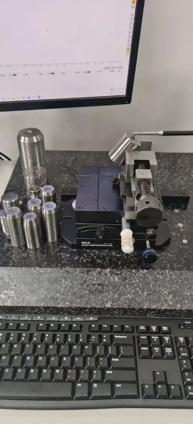
Rod side load is the silent killer. If the cylinder mounts off-axis from the slide guide by 1 to 2 mm over a 200 mm stroke, the rod packing sees bending load, the seal extrudes, and the cylinder fails while the mechanism still moves. Mount with dowel-pinned bosses and check alignment with a dial indicator across the full stroke before the hoses go on, accepting 0.05 mm or less of runout. The slide and wedge plates that carry those loads are ground to +/-0.005 mm as standard on our undercut and slide plates, the fit class that keeps a slide from chattering at end of stroke.
Hoses and fittings need a burst ratio of at least 2 to 1; on a 140 bar system that means 280 bar fittings minimum, which standard high-pressure BSP fittings satisfy. Rigid steel tubing inside the mold beats hose where the run is fixed: it cannot abrade, cannot fatigue-pulse at the clamp plate, and transfers less heat. Where a cylinder sits on the water side of the plate, condensation cycling through dew point corrodes carbon-steel bores in months; specify stainless tube or plated bores for cooled zones.
End-of-Stroke Positioning Accuracy
A core pull is a positioning device. The shut position sets the feature location, and a repeatable target of +/-0.01 mm keeps an undercut wall inside a 0.05 mm print. Hydraulics alone cannot deliver it: a cylinder stops where the flow dies, which varies 0.05 to 0.2 mm shot to shot with oil temperature. The accuracy comes from mechanics: a hardened stop block at the shut position, ground and lapped, that the slide indexes against before the wedge or lock takes the injection load.
The working chain has three stages. First the cylinder drives the slide to within 0.1 to 0.3 mm of shut, metered by a needle valve that slows the last 10 mm. Second, a taper draws the slide the final distance against the stop block, force at the end rather than at the start. Third, the lock wedge lands and the stop block carries no injection pressure. Repeat that chain with clean, lubricated surfaces and the scatter collapses to 0.005 to 0.01 mm; verify with a dial indicator on the core face over 100 dry cycles before the tool ships.
Thermal growth rides on top of the chain. A 300 mm steel slide between a cold day and a 90 degrees C production soak grows about 0.22 mm, and the core face moves with it. Do not chase that with the stop block: keep the slide short, let the plate soak evenly, and treat the steady-state shut position as the datum the drawing describes, verified in the trial after a 30 to 60 minute warm-up.
Failure Modes: Sticking, Late Sequence and Crushed Slides
The four failures that consume the most maintenance hours share a diagnosis order, so write it into the tool file before the first trial.
Sticking is the first. The slide moves in jerk-stop increments and the confirmation timer runs 10 to 50 milliseconds long. Root causes, in order: varnish from oxidized fluid at hot mounting faces, seal swell from an elastomer mismatch, and resin or scale on guide ways where flash lands on a moving shoe. The fix is a fluid change and filter element before a seal kit, and a scrape-and-inspect of the ways before anything is re-cut.
Late sequence shows up as a confirmation that arrives at 0.6 seconds when the machine window expects 0.4, and the press waits or alarms. Causes: a flow control someone "tuned", a pump delivering 125 bar instead of 140, a plugged timing orifice, or one cylinder stealing flow from a partner on the same line. Measure the supply pressure at the mold with all cylinders commanded; a sag over 10 bar is a plumbing problem, not a cylinder problem.
A crushed slide is the expensive one and it is a design failure, never a mystery: the mold closed while a core was not home. Either the sensor was bypassed to clear an alarm, the interlock checked one core instead of two, the low-pressure clamp window was shorter than the cam-out travel, or a hose burst and the cylinder back-driven. The countermeasures are cheap: series-wired sensors on every core, a low-pressure window sized so the platen stops before wedge contact, pilot-operated check valves at the ports so a hose failure parks the slide, and an alarm response that stops rather than continues.
The fourth mode is core wear at the shut position. A core that slams its stop at full cylinder pressure peens the steel, and after 200,000 to 500,000 cycles the shut position drifts 0.02 to 0.05 mm and the feature thickness walks out of print. Cushioned end-of-stroke and a hardened, replaceable stop strip push that interval past a million cycles. Nitrided or PVD-coated core faces also resist the abrasive grip of glass-filled resins, and a DLC layer of 1 to 3 micrometers follows the same coating rules used on lifters and lock wedges.
Maintenance Intervals and Spare Parts
Treat the pull system like the rest of the tool: intervals by shot count, documented in the maintenance sheet. Wipe and inspect the rod and gland daily; resin flash on the rod enters the seal the instant the cylinder retracts. Check confirmation timing weekly; a pull that has slowed 15 percent from baseline is two weeks from a stoppage. Grease the wedge and guide shoes every 25,000 shots, inspect seal faces, stop blocks and lock wedges at 50,000, and replace fluid and filter elements annually or at 500 operating hours.
Teardown intervals follow wear evidence, not the calendar. A seal kit on a 63 mm cylinder costs 100 to 300 USD and four hours of bench time; one running on an extruded seal mists oil into the part stream for a month. Re-grind or replace a wedge face when the contact pattern goes asymmetric or wear passes 0.05 mm, because after that point the core position error compounds with every cycle.
Spares for the tool file: one complete cylinder assembly per actuator type, two seal kits, one rod, one set of guide shoes, a spare angle pin or wedge, and the matched sensor with cable. Standard components ship in 3 to 7 days from our side, which means a planned spare costs a shift of downtime instead of a week of waiting. Put the spare list in the same maintenance sheet as the wedge and seal intervals so both reach the tooling tech on the same page.
Hydraulic Core Pull FAQ
Q1. What force does a hydraulic core pull need?
Start from the pull demand: core surface area times shrinkage grip of 2 to 4 MPa times a friction coefficient of 0.15 to 0.3, plus 0.5 to 2 kN of slide and wedge drag. Then size the bore at 140 bar so that demand sits under 70 to 80 percent of the friction-corrected cylinder force. A 30 kN demand points to a 63 mm bore, 43.6 kN theoretical at 140 bar.
Q2. What angle should the drive wedge be?
18 to 25 degrees from vertical for hydraulic reset wedges. At 20 degrees a wedge multiplies force about 2.75 to 1 ideal, and a 100 mm core withdrawal needs 151 mm of stroke-side travel. Below 15 degrees the travel demand grows faster than the force gain; above 25 degrees you lose more force than the travel saves.
Q3. How accurate can a hydraulic core pull repeat?
+/-0.01 mm at the shut position, achieved with a metered approach, a taper draw to a ground stop block, and a lock wedge for the injection load. Flow control alone gives 0.05 to 0.2 mm scatter and cannot hold a print dimension.
Q4. What interlocks protect a core pull from being crushed?
End-of-stroke sensors on every core wired in series with the high-pressure clamp step, a low-pressure clamp window covering the entire cam-out travel, relief valves at each port set 10 to 15 percent above working pressure, and an alarm response that stops the machine with the mold open instead of continuing the cycle.
Q5. When should a mold use hydraulic pulls instead of passive cams?
When the withdrawal exceeds about half the available mold opening, when cores longer than 5 times diameter grip the part, when two or more actions need a defined order, or when the path is multi-axis. Below those thresholds a cam costs less and fails less; the powered axis adds 2,000 to 6,000 USD per position plus plumbing and maintenance.
The Bottom Line
A hydraulic core pull is four numbers and one habit. Size the bore so demand stays under 70 to 80 percent of friction-corrected force at 140 bar: a 63 mm bore gives 43.6 kN theoretical and 31 kN of design budget. Set the wedge at 18 to 25 degrees and keep shoe contact pressure under 15 to 20 MPa. Interlock the clamp to sensors on every core with a low-pressure window across the full cam-out travel. Hold the shut position on a ground stop block, not on oil cushion, for +/-0.01 mm repeat. And log the confirmation timing weekly, because a pull that drifts 15 percent late is a crushed slide with a date already chosen.
DieStrike sequences hydraulic and passive side actions into precision injection and die-casting tools to IATF 16949 with +/-0.005 mm mold accuracy, HRC 62 maximum heat treatment and 120+ machines, with DFM feedback in 24 hours and tool lead times of 2 to 5 weeks. If your part has an undercut that a cam cannot reach, send the geometry and the cycle plan and we will return a pull layout with bore, angle and sensor map before the drawing set is cut.
KEEP READING
Related Reading
How to Design Ejector Systems: Pins, Plates and Timing
Force budgets, pin spacing and the ejection sequence that shares the same mold-open clock as your core pulls.
Read articleArticleHow to Select Side Locks: Wedge, Roller and Ball Types
Locking force, timing windows and the geometry that holds a hydraulic core at injection pressure.
Read articleArticleHow to Hold 0.002 mm Precision Mold Tolerances
Grinding, fits and inspection practice for the guide surfaces a core pull rides on.
Read articleProductUndercut and Slide Plate Components
Hardened slide and wedge components machined to +/-0.005 mm with standard items shipping in 3 to 7 days.
View componentsNEXT STEP
Ready to Start Your Mold?
Send us your element dimensions or part numbers — our team responds within 24 hours with pricing and lead time.

Written by
Ray ChanMold Buyer's Guide Author · Precision Mold Manufacturing Specialist. Ray helps global importers, distributors and OEMs source factory-direct molds and mold parts.