
Lifter vs Slide: How to Choose for Mold Undercuts
Table of Contents
A tooling team sized a slide for a 4 mm internal undercut on a connector housing with a 1.2 mm wall. A lifter could have released the same feature. The slide added about $3,200 to the tool cost and forced a mold base two sizes larger, which stretched delivery by 3 weeks. On another program the mistake ran the other way. A lifter was set on a 14 mm deep external undercut, the body bent around shot 900, and the repair cost $1,800 plus 5 days of lost production. Both failures trace back to one early decision: lifter vs slide, made before anyone checked the stroke math or the space envelope.
Every undercut in an injection mold needs a mechanism that moves perpendicular to the mold opening direction. The two workhorses are the lifter and the angle pin slide. They overlap on some geometry, but they differ hard on cost, stroke, strength, wear and the mold base they demand. Choosing wrong shows up as a bent lifter, a galled angle pin, flash on a shut-off face, or a mold base that never fit the machine. This guide gives you the judging criteria: undercut direction and depth, travel calculations, space limits, cost figures and failure modes, so the decision survives T1.
The Snapshot
- Typical cost per mechanism: $300-800 for a lifter, $1,500-5,000 for a complete slide assembly, industry figures for single-cavity tools.
- Practical undercut depth: lifters release up to about 10 mm, slides handle 10-150 mm and beyond.
- Angles: lifter body angle runs 5-15° typical, angle pin cam angle runs 15-25° typical.
- Stroke math: slide travel equals undercut depth plus 3-5 mm clearance. Lifter lateral travel equals ejector stroke times the tangent of the lifter angle.
- Cycle impact: slides add roughly 1-3 s of mold open and pin engagement time. Lifters move on ejection and add near zero.
How Mold Lifters Work
A lifter is an angled body that rides on the ejector system. Its head forms the undercut, and its foot sits in an angled slot or on a ramp in the mold core. When the ejector plate moves, the lifter travels up the ramp and swings sideways at the same time. That combined motion pulls the head out from under the plastic before the part leaves the core.
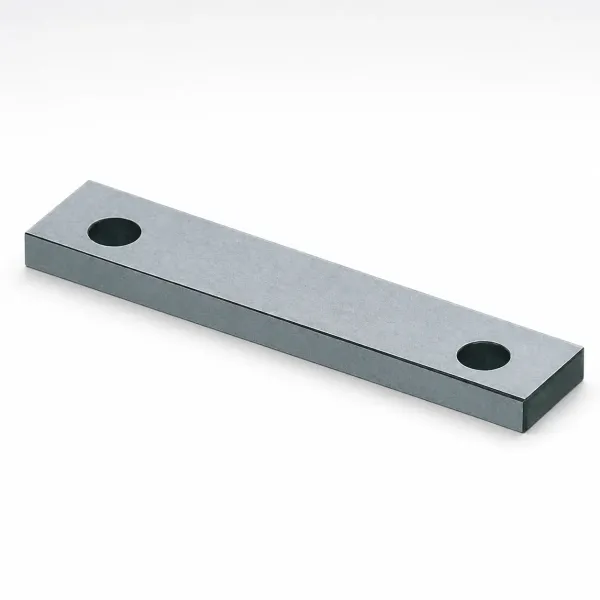
The geometry is compact. A lifter needs only its own thickness plus a few millimeters of clearance inside the core, so it fits where a slide cannot go. Typical lifter bodies are 10-40 mm wide and made from hardened steel around HRC 50-55, with the forming head often a separate insert for easy repair. Standard lifter components ship as catalog items from DME, HASCO and MISUMI in 3-7 days, which keeps them cheap and fast to replace.
Lifters also eject. Because the head is already pushing the part off the undercut, it doubles as an ejection surface. That removes one or two ejector pins from the layout and shortens the ejection sequence. On small internal features like snap hooks and rib windows, this dual role is the main reason lifters win.
The trade-off is force capacity. Lifter travel comes from the ejector stroke, usually 8-15 mm in production molds, so the lateral release is limited to a few millimeters. A long thin lifter body under side load from a stiff resin will deflect or bend. Undercut ejection with a lifter is a short-stroke, light-load mechanism, and it must stay that way.

Machining is straightforward. The lifter pocket is milled or EDM'd into the core, and the fit is held to about ±0.02 mm on the ramp surfaces so the body glides without rocking. At DieStrike, key mold dimensions are held to ±0.005 mm and mold part geometry to ±0.002 mm, which keeps lifter ramps running smooth over hundreds of thousands of cycles. Cavity steels are heat treated to HRC 62 where the resin is abrasive.
How Angle Pin Slides Work
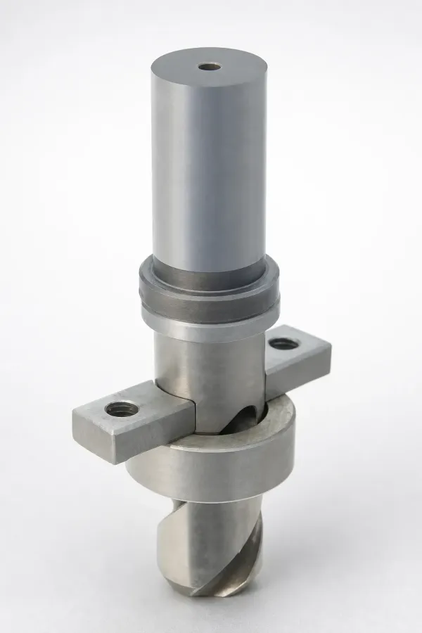
An angle pin slide, also called a cam pin slide or simply a slide core, moves a steel block sideways as the mold opens. The block rides on wear plates in the mold base. A hardened angle pin fixed to the stationary half enters a bushing in the slide block at 15-25°. Opening the mold drives the block outward along the pin, and the undercut clears before ejection starts.
Slides are strong. The block is supported across its full width by the mold base and locked by heel blocks or wear plates that take injection pressure, typically 30-80 MPa at the cavity surface. That support lets a slide carry deep undercuts, large forming areas and even multiple features on one block. External undercuts of 20-150 mm on automotive housings are normal slide territory.
The mechanism needs room. A slide adds width to the mold base on every side it occupies, and the angle pin needs straight length to fully engage. The full story on pin sizing, locking and wear plate design sits in our guide to how to design side actions. The short version: the mold base grows by the slide stroke plus the block length plus 20-30 mm of support, on each side.

Slides also need timing care. The slide must fully retract before the part is ejected, and fully close before injection, or the melt escapes into the gap and flashes. Locks, heel blocks and sometimes hydraulic cylinders enforce that order. Each extra item adds cost and a maintenance point that a lifter never has.
Lifter vs Slide: Cost and Lead Time
Cost is the clearest separator. A catalog lifter assembly, meaning the body, head insert, retainer and ramp fitting, typically runs $300-800 per unit, industry figures for standard sizes. A complete slide, meaning the block, angle pin, bushing, wear plates, heel block, locks and the extra mold base width, typically runs $1,500-5,000 per side. On a four-side tool with slides, the mechanism cost alone can reach $8,000-15,000 before any cavity steel.
Lead time follows the same gap. Lifters are mostly standard components plus one machined pocket, so they add days, not weeks. Slides add mold base resizing, angle pin fitting, lock timing and usually an extra assembly and tryout loop. At DieStrike, injection molds ship in 2-5 weeks with standard components like ejector pins, core pins, sprue bushings, mold springs and leader pins leaving the shelf in 3-7 days. A lifter-heavy design stays inside that window far more often than a four-slide design.
Maintenance cost tilts the same way. A worn lifter head is a small insert, often $50-150 and a few hours of bench work. A worn slide means re-fitting wear plates, re-matching the shut-off face and sometimes replacing the angle pin and bushing as a set, which runs $300-800 in parts plus press time. Over a 1 million shot program the delta compounds.
None of this means slides are wasteful. On a deep external undercut, a lifter is not an option at any price, and forcing one in produces a bent body and a scrapped core. The cost argument only applies where both mechanisms can physically release the feature. That question comes next.
Choosing by Undercut Direction and Depth
Direction is the first filter, and it is binary. An internal undercut, meaning a feature that traps the part on the core side like a snap hook, a side window or an inward rib, points toward a lifter. The mechanism sits inside the core and releases as ejection begins. An external undercut, meaning a feature on the cavity side or the part perimeter like a side hole, a latch pocket or an outer thread relief, points toward a slide. The steel must move away from the part before the mold opens fully.
Depth is the second filter. Lifters work well to about 5 mm of undercut and stretch to roughly 10 mm with a generous lifter angle and a stiff body, industry practice. Past 10 mm the required lateral travel exceeds a normal ejector stroke of 8-15 mm, and the body gets long enough to deflect under load. Slides take 10-150 mm routinely, and hydraulic slides or hand-loaded split cores go deeper still. Threaded features follow their own rules, covered in our guide to how to mold threads, where collapsible cores and unscrewing mechanisms beat both options.
Location matters too. An undercut near the parting line on the cavity half is natural slide territory. An undercut deep in a core pocket, far from any mold base face, cannot feed a slide block and must use a lifter or a hand-loaded insert. Undercuts on two opposite sides at once usually mean two slides, since a single lifter cannot release both directions.
Part material shifts the boundary as well. Stiff resins like glass-filled PBT or PPS grip the undercut hard, and demolding force climbs with glass content and surface area. A 6 mm undercut in unfilled ABS may release on a light lifter, while the same 6 mm in 30% glass-filled nylon needs the extra strength and full support of a slide, or at minimum an oversized lifter body with a hardened head insert.
Stroke and Draft Calculations
Slide stroke is simple arithmetic. Required travel equals the undercut depth plus 3-5 mm of clearance so the steel fully frees the part. A 12 mm undercut needs 15-17 mm of slide travel. The angle pin then sets the mold opening distance: opening equals travel divided by the cosine-adjusted pin geometry, and a 20° pin needs roughly 1.1 times the travel measured along the pin axis. Steeper pins, up to 25°, shorten opening but raise the side load on the wear plates by about 30% versus a 15° pin.
Lifter stroke is a triangle problem. The lifter body angle typically runs 5-15°. Lateral travel equals the ejector stroke times the tangent of that angle. A 12 mm ejector stroke at a 12° lifter angle gives 12 times tan 12°, or about 2.5 mm of lateral release. To free a 4 mm undercut at the same angle you need a 19 mm ejector stroke, which many mold bases cannot provide without special spacers.
Draft angle decides how much of that release is real. Every degree of draft on the undercut face cuts the needed lateral travel. With 1° of draft on a 4 mm deep undercut over a 20 mm feature length, the effective interference drops by roughly 0.35 mm. The common drafting errors that trap mechanisms are listed in our guide to 9 draft angle mistakes. A lifter design with zero draft on the undercut is a design that will gall, drag and eventually fail.
Two checks close the calculation. First, confirm the ejector stroke available in the chosen mold base exceeds the lifter requirement by at least 3 mm. Second, confirm the mold opening stroke on the target machine exceeds the slide engagement plus safety, typically opening travel plus 25-50 mm. Either check failing means a bigger mold base, a different angle, or a different mechanism.
Mold Base Space Constraints
Slides eat mold base in three directions. Sideways, each slide adds its stroke plus block length plus 20-30 mm of support to the base width. Vertically, the angle pin needs engagement length inside the block, usually 1.5 to 2 times the pin diameter, which can force spacer blocks between the B plate and the backing plate. Along the opening direction, the heel block and locks occupy the parting line region where cooling lines would otherwise run.
Lifters eat core real estate instead. Each lifter needs a pocket roughly 1.5 times the body width, machined into the core at the correct angle. On a multi-cavity mold, lifters multiply: two lifters per cavity on a 4-cavity tool means 8 pockets, and the core becomes a crowded maze of ramps and retainers. Core strength drops as pockets multiply, so wall thickness between pockets should stay above 15-20 mm to avoid deflection under injection pressure.
Cooling takes the hit either way. Slide blocks rarely carry conformal lines, so the undercut region cools through the shut-off face and the base, often adding 2-5 s to cycle on thick sections near the slide. Lifter bodies can carry a baffle or bubbler line if the body is 20 mm wide or more. Budget the cooling early, because a mechanism that fits but starves the part of cooling will fail the cycle time target at T1.
The machine check comes last. A four-slide tool can grow the mold base by 80-120 mm in width versus a lifter design for the same part family. That growth pushes tie-bar spacing, platen coverage and clamp tonnage limits. A mold that clears the space on paper but not the machine is a dead design, so verify against the target press before the base order ships.
Failure Modes Compared
Each mechanism fails in its own signature ways, and the failure list doubles as an inspection list at T1 and at every mold maintenance window. Lifters fail from overload and wear at the ramp. Slides fail from timing, galling and lock wear. Knowing the top modes for each mechanism tells you which one your part, resin and volume can tolerate.
| Failure mode | Lifter | Angle pin slide |
|---|---|---|
| Body or block deformation | Bends above about 10 mm undercut depth, common with glass-filled resins | Rare, block fully supported by heel blocks and wear plates |
| Wear surface | Ramp and retainer slot, galling after 100k-300k cycles without lubrication | Angle pin bushing and wear plates, greased fittings extend life past 500k cycles |
| Timing failure | Moves with ejection, almost no timing risk | Slide not fully closed before injection causes flash on the shut-off face |
| Drag on release | Head drags if draft under 0.5-1° or if shrink grips the core | Drag minimal, stroke is driven by mold opening force |
| Repair difficulty | Head insert swap, hours of bench work, $50-150 parts typical | Pin, bushing and wear plate re-fit, days in press, $300-800 parts typical |
← swipe to scroll →
Table note: Failure thresholds and costs are industry-typical figures for single-cavity tools running standard engineering resins at normal volumes.
The bend failure deserves a closer look because it is the most expensive. A lifter sized for a 12 mm undercut in 30% glass-filled nylon sees demolding forces that scale with the glass content and the undercut area. The body acts as a cantilever, deflection grows with the cube of length, and a 60 mm long lifter deflects 8 times more than a 30 mm one at equal load. Once the body bends, the head no longer seats, the shut-off leaks and flash appears inside the part. The fix is a slide, or a redesigned part with the undercut reduced below 5 mm.
Slide timing failures show up differently. If a lock wears by 0.1 mm, the slide closes late and melt escapes along the parting face. The flash is thin, often under 0.05 mm, so it passes visual inspection for a while and then grows into a scrap problem. Checking lock contact with blueing compound every 50k shots, or at each maintenance window, catches it early. Lifters have no equivalent wear path, which is one more reason they suit high-mix, low-attention tools.
Wear: Materials and Coatings
Lifter bodies run on P20 hardened to HRC 28-32 for prototyping work, or H13 and S136 at HRC 48-55 for production volumes above 500k shots. The head insert takes the abuse and is usually made separately in hardened tool steel so it can be replaced without scrapping the body. Ramp surfaces in the core are often fitted with hardened wear plates, 5-8 mm thick, bolted into the pocket.
Angle pins are catalog standard, made from hardened steel around HRC 58-62 with a ground surface finish near Ra 0.2 µm. Bushings are bronze or hardened steel depending on cycle count. Wear plates under the slide block use hardened steel with grease channels, and the grease fittings are the single cheapest life extension on any slide tool. Unlubricated slides gall at 100k-200k cycles. Lubricated slides run past 500k without re-fitting, industry figures.
Coatings pay off on abrasive resins. Glass-filled materials score bare steel quickly, and a TiN or DLC coating on the lifter head or the slide shut-off face cuts wear by 3-5 times on 30% glass-filled nylon programs. The coating decision follows the same logic as elsewhere in tooling, with the payoff threshold around 300k cycles for glass-filled resins. On unfilled resins below 200k lifetime shots, coatings rarely return their $400-900 cost per component.
Cycle Time and Ejection Sequence
Slides run inside the mold open and close window. The angle pin only engages after the mold separates by the pin lead distance, usually 5-15 mm of opening. At a typical opening speed of 100-200 mm/s, each slide pair adds roughly 1-3 s of dry cycle, and hydraulic slides that retract before opening add more. On a 20 s cycle that is a 5-15% output loss, which at 24/7 running equals thousands of parts per year.
Lifters ride the ejector stroke, which the machine already performs. Lateral release happens in the first 3-8 mm of ejection, and the extra dry time is near zero. For high-volume programs where every second of cycle counts, lifters hold a real advantage on any undercut they can physically release. The ejection system layout around them still matters, and the force and stroke math is covered in our guide on how to design ejector systems.
Sequence control separates good designs from fragile ones. On a slide tool, ejection must not begin until the slide is fully retracted, and most molds enforce this mechanically through the mold base geometry or electrically through limit switches tied to the press. On a lifter tool, the lifter must release before the main ejector pins push the part, so lifter ramp travel comes first in the stroke, usually the initial 20-30%. Getting either sequence wrong produces crushed parts or torn undercuts on every cycle, not occasionally.
Multi-cavity balance adds one more check. Lifters in different cavities wear at slightly different rates, and by 300k shots one cavity may release 0.05 mm later than the others. That drift shows up as inconsistent witness marks near the undercut. Slides share one timing source per block, so cavities behind the same slide stay in sync by construction.
The Decision Matrix
Put the criteria into one table and most parts sort themselves. Score each row against your part drawing: direction, depth, location, resin, volume and mold base room. The mechanism with the most wins is your default, and the exceptions are worth an explicit engineering note.
| Decision factor | Choose lifter when | Choose slide when |
|---|---|---|
| Undercut direction | Internal, core side | External, cavity side or perimeter |
| Undercut depth | Up to 5 mm ideal, 10 mm max | Above 10 mm, or any depth to 150 mm |
| Location in mold | Deep in a core pocket, no base access | Near a mold base face, block can be fed |
| Resin stiffness | Unfilled or lightly filled grades | Glass-filled PBT, PPS, nylon above 20% GF |
| Budget per feature | $300-800 typical | $1,500-5,000 typical accepted |
| Cycle time target | High volume, every second counts | 1-3 s per cycle acceptable |
| Mold base room | Base width fixed, machine limited | 20-30 mm extra width per side available |
| Maintenance access | Low attention tool, no grease program | Scheduled lubrication every 50k shots possible |
← swipe to scroll →
Table note: Cost figures and depth thresholds are industry-typical values for single-cavity production tooling, so verify against your mold base series and target press.
Two gray zones deserve notes. First, a 6-10 mm internal undercut in a stiff resin can go either way: a heavy lifter with a hardened head and a wear plate ramp will run, but a slide is the conservative pick above 500k shots. Second, small external undercuts under 3 mm can sometimes be released by shut-off compression or by flexible resin deflection, which beats both mechanisms at zero cost. Connector OEMs including TE Connectivity, Amphenol and Luxshare routinely spec latch undercuts in this gray band, and the DFM review is where the call gets made.
Whatever the matrix says, the numbers get verified before steel is cut. Stroke math against the actual mold base, space against the actual press, forces against the actual resin. A DFM report that omits the mechanism check is incomplete, and at DieStrike that feedback lands within 24 hours of drawing receipt.
FAQ
Q1. How deep an undercut can a mold lifter release?
About 5 mm comfortably and roughly 10 mm at the limit, industry practice. Lateral travel equals ejector stroke times the tangent of the lifter angle, so a 12 mm stroke at 12° gives only 2.5 mm of release. Deeper undercuts need a longer stroke, a steeper angle or a slide.
Q2. What does a slide cost compared to a lifter?
A lifter assembly typically runs $300-800. A complete slide with angle pin, bushing, wear plates, heel block and locks typically runs $1,500-5,000 per side, industry figures. The slide also grows the mold base, which adds cost downstream.
Q3. Can I use a lifter for an external undercut?
Rarely. External undercuts sit on the cavity side, where the steel must move before the mold opens, and a lifter only moves during ejection on the core side. External features almost always need a slide, a split core or a hand-loaded insert.
Q4. Which mechanism adds less cycle time?
The lifter, by 1-3 s per cycle in most molds. Lifters ride the existing ejector stroke at near-zero added time, while angle pins engage only after 5-15 mm of mold opening. On a 20 s cycle that gap is worth 5-15% of output.
Q5. How do I size the angle pin for a slide?
Cam angle stays within 15-25°, with 20° a common default. Pin diameter scales with slide mass and injection pressure, typically 16-32 mm for production tools, and engagement length inside the block runs 1.5 to 2 times the diameter. Full sizing rules are in the side actions design guide linked above.
The Bottom Line
Lifters win internal undercuts under 10 mm on cost, cycle and simplicity. Slides win everything deeper, stiffer or external, at 3-6 times the price. Pick by direction and depth first, verify stroke and space math second, and never let an unproven mechanism reach T1. DieStrike builds IATF 16949 precision molds with ±0.005 mm key dimensions, 2-5 week lead times and DFM feedback within 24 hours, so the lifter-vs-slide decision gets settled on the drawing, not on the press. If an undercut is driving your next tool quote, talk to our engineering team before you commit to a mechanism.
KEEP READING
Related Reading
How to Design Side Actions: Slides, Angle Pins and Locking
Slide geometry, angle pin sizing, wear plates and locking rules for side actions in injection molds.
Read articleArticleHow to Design an Ejector System: Pin Layout, Force and Stroke
Ejector pin layout, ejection force and stroke calculations that decide whether a lifter can release your part.
Read articleArticle9 Draft Angle Mistakes That Kill Moldability
Nine draft angle errors that cause drag marks, sticking and failed releases on lifter and slide surfaces.
Read articleServiceMold Design and DFM
DFM feedback within 24 hours, including undercut mechanism selection, stroke checks and tooling cost review.
Read articleNEXT STEP
Ready to Start Your Mold?
Send us your element dimensions or part numbers — our team responds within 24 hours with pricing and lead time.

Written by
Ray ChanMold Buyer's Guide Author · Precision Mold Manufacturing Specialist. Ray helps global importers, distributors and OEMs source factory-direct molds and mold parts.