
How to Design Molds for EV Battery Housings and Module Frames
Table of Contents
A 1.8 mm PC/ABS battery cover can pass UL 94 V-0 and still leak at 0.2 bar. A 0.03 mm step opened on the sealing face. The same tool can drop out of a ±0.05 mm wall window after 30,000 shots. A 60 mm cavity plate that bows 0.15 mm under 900 bar does the same. Battery housing molds fail for tooling reasons, not molding reasons. Every decision below carries a number, because packaging a 1.2 to 2.5 mm wall into a 1,200 mm long part leaves almost no error budget.
The Snapshot
- Wall range 1.2 to 2.5 mm on parts up to 1,200 mm long. Flatness is held at 0.3 mm or tighter across the sealing face.
- Materials in scope: PC/ABS V-0, PA66-GF30 and PP-LGF long glass fibre, all rated UL 94 V-0 and specifying CTI from 250 to 600 V.
- Cavity plate thickness 60 to 130 mm, support pillar spacing 120 to 220 mm, sized against 350 to 1,000 bar peak cavity pressure.
- Weld-line strength behind ribs and bosses drops to 40 to 60% of virgin tensile strength in 30% glass-filled resin.
- Mold accuracy ±0.005 mm and component geometry ±0.002 mm, with cavity hardness at HRC 62. DFM feedback comes back in 24 hours and mold lead time runs 2 to 5 weeks.
Why EV Battery Housing Tooling Is Different
An EV battery housing is a structural enclosure, a thermal barrier and a dielectric wall at the same time. It must survive 200 kN crush loads and hold an IP67 seal at 0.5 bar for 30 seconds. It also has to keep CTI above 250 V between the module frames and the pack floor. Tooling that treats it as a large box will not hold those three jobs together.
Size sets the error budget. A 900 mm module frame grows about 0.9 mm over a 60 °C service swing. Glass-filled PA66 sits near 17 ppm per °C, and that coefficient drives the growth. That leaves wall thickness variation as the dominant risk, not thermal growth. Tool builders therefore target 0.3 mm flatness on the sealing face and ±0.05 mm on wall sections.
The tool carries the leak risk. Sealing faces are shut-off surfaces. Any parting-line mismatch above 0.02 mm becomes a leak path. So does plate deflection that opens the seal during fill, or a weld line that crosses the seal path. A leak test at 0.2 to 0.5 bar finds these defects in seconds. The fix therefore has to live in the steel.
Cycle time dominates cost. A 2.0 mm wall cooled from 250 °C to 80 °C needs 35 to 50 seconds of cooling in a well-designed circuit. Poorly placed baffles or a 25 mm channel pitch can add 15 seconds, which at 500,000 parts per year equals thousands of machine hours. This is why cooling layout belongs in the mold design review, not in the trial.
For teams weighing this tooling against laminated metal or die-cast alternatives, the tooling logic in the EV and energy industry page covers the pack-level trade-offs. Everything below assumes the plastic route is fixed and the question is how to cut the tool.
Material Selection for V-0 Housings and Module Frames
Resin choice drives steel choice, gate choice and the coefficient of thermal expansion used in the shrinkage model. Three families cover most EV battery programs, and each one loads the tool differently.
PC/ABS with a V-0 package. Typical shrinkage runs 0.5 to 0.7%, tensile strength 55 to 65 MPa, and CTI between 250 and 400 V depending on the additive package. The blend is tough and dimensionally stable, so it suits covers and low-voltage module frames. It also absorbs moisture, so drying to below 0.02% before any trial is mandatory. Polish the cavity to resist splay marks on a visible surface.
PA66-GF30. Shrinkage drops to 0.3 to 0.7% with strong anisotropy, tensile strength rises to 160 to 185 MPa, and CTI reaches 400 to 600 V. This is the standard choice where the housing carries fastener loads and creepage distance to busbars. Glass fibre abrades steel, so gates, runners and any melt-facing insert need HRC 60 or harder surfaces and a wear allowance.
PP-LGF long glass fibre. Shrinkage is low, 0.2 to 0.5%, and directional, and impact performance holds down to -30 °C. Long fibres break when they pass a sharp corner, so the tool must use wide gates, generous radii and no sudden area change. Fibre attrition is a cavity-side responsibility, not a resin-side one.
| Material | Wall range | Shrinkage (typical) | Flammability / CTI | Tooling consequence |
|---|---|---|---|---|
| PC/ABS V-0 | 1.8 to 2.5 mm | 0.5 to 0.7% | UL 94 V-0 at 1.5 mm, CTI 250 to 400 V | Polish cavities to SPI B1 minimum, dry resin below 0.02% |
| PA66-GF30 | 1.5 to 2.5 mm | 0.3 to 0.7%, anisotropic | V-0 with FR package, CTI 400 to 600 V | HRC 60+ gates, 0.03 mm wear allowance on runners |
| PP-LGF30 | 1.2 to 2.0 mm | 0.2 to 0.5%, flow direction | V-0 with FR, CTI up to 600 V | Wide fan gates, R2 mm minimum, no sharp turns |
| PA66-GF50 | 1.5 to 2.5 mm | 0.2 to 0.4% | V-0 with FR, CTI 500 to 600 V | Carbide or PVD-coated gate inserts, 0.05 mm allowance |
| PC V-0 | 2.0 to 2.5 mm | 0.5 to 0.7% | V-0 at 1.5 mm, CTI 250 V | Oversized gates and vents for high melt viscosity |
← swipe to scroll →
Table note: shrinkage and CTI values are typical published ranges for flame-retardant grades and vary by supplier and additive package. Confirm against the resin data sheet before freezing the shrinkage model.
Two choices matter more than the rest. First, CTI sets the minimum wall between live metal and any grounded surface, so it feeds the creepage geometry that the tool must mold. Second, anisotropy means a single shrinkage value cannot be applied in every direction. Model flow and cross-flow shrinkage separately or the module frame will twist.
Thin-Wall Stiffness: Plate Thickness and Support Pillars
A 1.2 mm wall demands high injection pressure. That pressure pushes back on the cavity plate, and the plate answers with deflection. If the plate bends more than 0.05 mm, wall thickness leaves its window and the sealing face opens.
Cavity plate thickness. A 900 mm module frame running 700 to 1,000 bar peak pressure usually takes a 60 to 90 mm cavity plate in P20 or 1.2343. Below 60 mm the deflection budget is gone unless the tool uses a full support frame. Above 130 mm the plate becomes a handling problem without adding accuracy.
Support pillars. Pillars sit between the support plate and the cavity plate. Space them 120 to 150 mm apart for thin walls and 180 to 220 mm for 2.0 to 2.5 mm walls. A pillar pattern that skips the center of a 900 mm frame lets the middle flex. That is the classic source of a 0.1 mm wall bulge at mid-length.
Backing plates and shims. The support plate must be flat to 0.02 mm across its length before assembly. Shim stacks above 0.05 mm total thickness should be replaced with a ground pillar. Stacked shims compress over 100,000 cycles and the deflection returns.
Cavity inserts versus a solid cavity. Bolt-on inserts with 0.02 mm interference fits hold wall geometry better on long frames. They also let a worn gate area be replaced without recutting the whole block. For the largest housings, an insert strategy also shortens lead time because the main block can be roughed in parallel.

Deflection is measurable. Before cutting pockets, a simple beam calculation over the pillar span gives the answer within 10%. If the predicted deflection exceeds 0.05 mm at peak cavity pressure, add pillars or thicken the plate. Steel is cheaper than a scrap battery housing program.
A second check is thermal. The cavity plate runs at 60 to 90 °C for these resins while the support plate below stays near 40 °C. A 50 °C differential across a 90 mm plate shifts its length by about 0.08 mm on a 900 mm frame. Side locks and leader pins absorb that movement, but only if the alignment system is sized for it.
Cavity Pressure Distribution and Clamp Load
Peak cavity pressure is not uniform. It is highest near the gate and lowest at the last-fill corner, and on a large frame the difference can exceed a factor of three. The tool must be designed for the peak, while the molding window is set from the average.
Pressure estimate. A rough rule is 300 to 500 bar for thick, easy-flow sections. Thin 1.2 to 1.6 mm walls in glass-filled resin run 700 to 1,000 bar. A 0.6 m² projected area at 800 bar produces about 480 tonnes of separating force, so clamp tonnage and press selection follow directly.
Where the tool fails. If clamp tonnage sits under 20% above the requirement, the parting line lifts near the gate. Flash then appears on the sealing face, and a few hundredths of a millimetre is enough. That flash is a leak path, not a cosmetic issue. The warpage rules for thin-wall molds cover how the same pressure field distorts the part after ejection.
Balance across cavities. A 2-cavity module frame tool with unequal runner resistance fills one side first and holds 200 to 300 bar more pressure there. The result is a 0.1 mm dimensional split between the two parts. Balance the runner on calculated pressure drop, not on equal lengths.
Venting is part of the pressure problem. Air that cannot leave traps pressure at the last-fill point an additional 100 to 200 bar. Vent depths of 0.02 to 0.03 mm for PC/ABS and 0.01 to 0.02 mm for glass-filled PA66 at the fill end keep the peak predictable.
Machine compatibility matters as much as tonnage. Tie-bar spacing, platen size, ejector pattern and the location of the sprue must all be checked against the actual press. A 4 tonne tool that fits the crane but not the platen wastes a trial slot.
Gate Layout and Weld-Line Strength
On a structural housing, the weld line is the weakest point in the part. Glass-filled resin at a weld line loses 40 to 60% of its tensile strength. The fibres align parallel to the meeting front instead of crossing it. Design the gate layout to move weld lines out of load paths.
Gate position first. A single gate on a 900 mm frame forces a long flow path. It also creates a weld line where the flow wraps around a core or boss. Two or four gates shorten the path, lower the pressure requirement, and give you control over where the fronts meet. When two fronts must meet, place the junction in a low-stress web rather than behind a fastener boss.
Gate size. Undersized gates shear long fibres and raise the risk of splay. For PP-LGF, use a fan gate with a 1.5 to 2.5 mm land. A width equal to 30 to 50% of the part edge keeps shear low. For PA66-GF30, a 1.0 to 1.5 mm gate diameter is workable. Plan for wear, because the gate erodes and the fill pattern drifts over 100,000 cycles.
Valve gates versus thermal gates. A sequential valve gate system lets you start one gate, then open the second after the first front passes. This converts an uncontrolled weld line into a controlled one and typically recovers 15 to 20% of weld-line strength. On battery module frames it also reduces the pressure peak at the last-fill corner.
Tooling moves that help. Increase local wall thickness by 0.1 to 0.2 mm at the weld-line location. Add a small overflow or vent at the meeting point. Raise the local mold temperature by 10 to 15 °C with a dedicated circuit. Each of these costs cycle time, so they belong only where the load path actually runs. The broader gate placement logic sits in the weld line reduction guide.

Verify before steel. A fill analysis of the weld-line location costs a fraction of a trial cycle and predicts where the fronts meet within a few millimetres. Once the tool is cut, the only remaining lever is temperature, and that lever is small.
Gate and Runner Wear with Long Glass Fibre
Long glass fibre is abrasive in a way that unfilled resin is not. A 30% LGF melt at 250 to 290 °C carries fibre bundles that erode gate lands, runner walls and hot-runner tips. Wear changes the fill pattern, and a changing fill pattern changes weld-line position over the life of the tool.
Where wear concentrates. Gate lands lose 0.02 to 0.05 mm of material within 100,000 shots on an uncoated P20 gate insert. Hot-runner nozzle tips wear faster. Runner direction changes and any sharp corner see the highest erosion rate because fibre velocity peaks there.
Steel choices. Use HRC 60 to 62 through-hardened inserts at the gate, or coat them. PVD coatings such as TiAlN and DLC extend gate life two to three times on glass-filled work. This holds only if the substrate is hard enough to support the coating. The wear mechanisms and steel pairings for filled resins are covered in the glass-filled resin tooling guide.
Runner design for long fibre. Use full-round runners with a diameter of 6 to 10 mm for large housings, keep the length short, and avoid sudden expansions. Every sharp turn costs fibre length, and shorter fibres mean lower impact strength in the molded part. Radius all corners at 3 mm minimum.
Design for replacement. Make the gate insert a separate bolted block, not part of the main cavity. A 50 mm gate insert costs far less to replace than a full cavity recut. It also lets you re-tune gate size in the field after 200,000 shots. This single decision saves weeks in the third year of a housing program.
Wear monitoring. Track shot count against a dimensional check of a molded witness feature. When the gate land has worn 0.05 mm, filling shifts and dimensional drift appears. Schedule the insert replacement from that data, not from a calendar.
Cooling and Cycle Time for 1.2 to 2.5 mm Walls
Cooling controls 60 to 70% of the cycle on these parts. A 2.0 mm wall in PA66-GF30 needs roughly 35 to 50 seconds to reach an 80 °C ejection temperature. Every design choice in the circuit either protects that number or destroys it.
Channel size and pitch. Use 12 to 16 mm channels with a centerline distance of 2.5 to 3.5 times the diameter, typically 30 to 50 mm. Closer pitch improves uniformity but weakens the plate. On a long frame, run channels along the flow direction so temperature follows the fill pattern.
Thin walls need turbulent flow. Reynolds number above 10,000 keeps heat transfer stable. That usually means 40 to 60 L/min per circuit on a large housing, which drives the choice of mold temperature controller and manifold size. Laminar flow in a 14 mm channel at 15 L/min adds 10 to 20 seconds of cycle time without warning.
Baffles and bubblers. Deep cores and tall bosses need baffles or bubblers to reach the interior. A correctly sized bubbler can cut local cooling time by 40% compared with a straight drilled channel that stops short. Ejection temperature variation across the part is the leading cause of post-mold warp.
| Wall thickness | Peak cavity pressure (typical) | Cavity plate | Support pillar pitch | Target cooling time |
|---|---|---|---|---|
| 1.2 to 1.6 mm | 700 to 1,000 bar | 60 to 80 mm P20 or 1.2343 | 120 to 150 mm | 25 to 40 s |
| 1.6 to 2.0 mm | 500 to 800 bar | 80 to 100 mm | 150 to 180 mm | 35 to 50 s |
| 2.0 to 2.5 mm | 350 to 600 bar | 100 to 130 mm | 180 to 220 mm | 45 to 70 s |
← swipe to scroll →
Table note: pressures and cooling times are typical values for unfilled and glass-filled engineering resins in the stated wall range. Confirm with a cavity pressure study during the trial before locking cycle time into a quotation.
Keep the seal cool, not cold. Sealing faces should run within 10 °C of the adjacent wall. A locally cold sealing face chills the melt front, causes a short seal lip, and produces a leak path that no pressure test will forgive.
Sealing Faces and Leak-Test Requirements
Battery housings are pressure vessels in miniature. IP67 requires no water ingress at 1 m for 30 minutes. Many OEMs add a 0.2 to 0.5 bar air decay test with a leak limit of 5 to 20 cc/min. The tool determines whether that limit is reachable.
Sealing face geometry. A flat sealing land 3 to 6 mm wide with a defined surface finish works better than a knife edge. Knife edges chip, and a chipped edge is a permanent leak. Target Ra 0.8 to 1.6 µm on the land and keep the land continuous around the full perimeter.
Parting line control. Shut-off mismatch above 0.02 mm opens a path. The tool must have a positive shut-off, usually a 3 to 5° angle on the male side into a matching pocket. Side locks carry the alignment load. Leader pins alone do not hold a 900 mm frame in register.
Weld lines on the seal path. Never let a weld line intersect the sealing land. A weld line on the land has 40 to 60% of virgin strength. It will fail a fatigue test long before a static leak test finds it. Move gates or split the flow so the junction lands in the interior web.
Test both ways. Verify the tool with air decay at 0.5 bar, then confirm on a sample with a dye penetrant check at the sealing land. A tool that passes air but shows penetrant wicking has a shut-off that will open after 50,000 cycles. Fix it during the trial with a welded and re-machined shut-off, not in production.

Vents must not cross the seal. A vent that runs off the sealing land acts as a leak channel. Terminate venting 2 to 3 mm short of the land, or route it to a dedicated vent block that seals on its own face.
Dimensional Control and Traceability
A battery housing carries a flatness callout of 0.3 mm, a wall tolerance of ±0.05 mm and hole positions within 0.2 mm. Those numbers must be traceable back to the tool, not just reported on the part.
Tool datums first. Define the mold datum scheme before machining, with three primary datum pads on the cavity plate and two secondary edges. Every insert, pillar and cooling line is then measured from the same reference. Without this, a CMM report on the part cannot be traced to a specific tool error.
Steel measurement. The cavity block is measured to ±0.005 mm overall mold accuracy, with critical component geometry to ±0.002 mm. Channels, guide holes and ejector patterns are verified on the plate. A 0.02 mm misalignment in a pillar bore shows up as a wall variation in the molded part.
Part measurement. Use a fixture that reproduces the mounting condition. A 900 mm frame measured flat on a granite table reads differently when clamped at the pack interface. Report flatness under the same constraint the OEM uses. For a walk-through of the data format, see the CMM reading guide in the related articles.
Traceability chain. Record the tool number, insert serial, heat-treatment lot, steel grade and first-article dimensions against the part serial. IATF 16949 requires this chain for automotive programs. It pays off during a field failure investigation, where the question is which cavity produced the part.
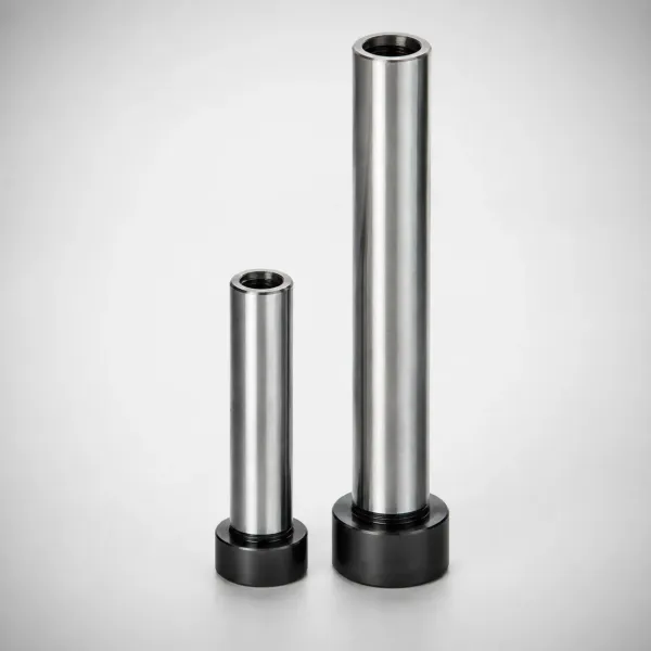
Capability, not conformance. A first article shows the part is inside tolerance once. A capability study over 30 consecutive shots shows Cpk. Target Cpk 1.33 minimum on wall thickness and flatness before releasing the tool to production. Below that, the tool will drift out of tolerance within the first production order.
Handling and SPI Interfaces Above 2 Tonnes
A housing tool for a 900 mm frame commonly weighs 2,500 to 8,000 kg. Above 2 tonnes, handling, lifting and utility connection become design constraints, not logistics afterthoughts.
Lifting points. Four lifting eyes sized for the full tool weight with a safety factor of 4, positioned so the tool hangs level within 3°. Off-center lifting tilts the tool and puts the alignment pins at risk during installation. Check the eye positions against the actual center of gravity after assembly, not from the drawing.
Platen interface. Specify bolt patterns, clamp slots and locating rings that match the target press. A 1,200 mm platen needs at least six clamp points per side to prevent tool shift under 480 tonnes of separating force. Add a safety strap specification to the drawing so the customer has one answer for the press shop.
SPI utility connections. Standardize the water manifold, air line, thermocouple junction and electrical box layout to SPI conventions. Label every circuit with flow, temperature, and pressure rating. A 900 mm frame tool often runs 8 to 14 separate circuits. Mislabeled circuits are a common cause of a bent tool during first installation.
Moving and storage. Provide lifting bars and a base frame that allows forklift access from all four sides. Add a storage stand that supports the tool on the support plate rather than the cavity. Storing a 4 tonne tool on its cavity face risks a 0.05 mm dent that shows up as flash in the first production run.
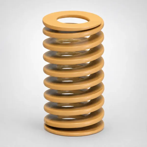
The design and DFM service covers the tool-to-press compatibility check before steel is ordered, with 24 hour feedback on the part geometry. It is cheaper to move a lifting eye on a drawing than on a finished 4 tonne block.
Maintenance and Cavity Life on Large Tools
Housing molds run 200,000 to 1,000,000 shots on a platform program. Planned maintenance turns that range into a real-life number, and unplanned maintenance turns it into scrap.
First year. Check gate insert wear every 25,000 shots on glass-filled resin, and re-polish the sealing land every 50,000 shots. Confirm pillar shim stack thickness at 100,000 shots because compression changes the deflection behavior the tool was designed around.
Cooling circuit care. Scale builds 0.1 to 0.3 mm per year in untreated water circuits. Flow loss above 20% from baseline means the circuit needs cleaning, not a higher setpoint. Track inlet-to-outlet temperature difference per circuit on every run, because that number falls before cycle time visibly changes.
Erosion and repair. Weld repair on a housing cavity is acceptable on non-sealing surfaces. Preheat the cavity to 200 to 300 °C and apply post-weld heat treatment. Never weld across a sealing land. Replace the land with a new insert instead.
Replacement parts. Keep spare ejector pins, core pins, leader pins and bushings in stock. Standard components ship in 3 to 7 days, which keeps a planned weekend maintenance slot from turning into a two week downtime event. That difference in uptime usually exceeds the cost of the whole spare parts inventory.
FAQ: EV Battery Housing and Module Frame Molds
Q1. What wall thickness should an EV battery housing use?
Most programs run 1.2 to 2.5 mm. Thin sections of 1.2 to 1.6 mm in PP-LGF suit large covers where weight matters. They push cavity pressure to 700 to 1,000 bar and demand 60 to 90 mm cavity plates. Sections of 2.0 to 2.5 mm are more forgiving at 350 to 600 bar and are common where the frame carries fastener loads.
Q2. How do I stop a weld line from leaking on the sealing face?
Never let a weld line cross the sealing land. Use two or four gates with sequential valve gate control so the flow fronts meet in an interior web. A controlled weld line recovers 15 to 20% of strength compared with an uncontrolled one, and the seal path stays solid.
Q3. How much support pillar spacing does a 900 mm frame need?
Use 120 to 150 mm spacing for 1.2 to 1.6 mm walls and 180 to 220 mm for 2.0 to 2.5 mm walls. Confirm by beam calculation that predicted deflection at peak cavity pressure stays below 0.05 mm. If it does not, add pillars before cutting pockets.
Q4. Can the same tool run PC/ABS and PA66-GF30?
Not without changes. Shrinkage differs by 0.2 to 0.4 percentage points between the two, and PA66-GF30 wears a gate that PC/ABS does not. A tool designed for PC/ABS will produce out-of-tolerance PA66-GF30 parts on the first shot and lose its gate land faster. Pick the resin before the shrinkage model is frozen.
Q5. What lead time should I plan for a battery housing mold?
Plan 2 to 5 weeks for the mold itself once the design is approved, with DFM feedback inside 24 hours. Standard components such as ejector pins, leader pins and bushings ship in 3 to 7 days, so they rarely drive the schedule. The long pole is usually cavity machining and the T1 sample slot.
The Bottom Line
Battery housing molds fail on three numbers. Plate deflection above 0.05 mm, a weld line on the sealing land and a gate worn past 0.05 mm all end a program early. Control those and the tool holds IP67 and dimensional capability for the platform life. DieStrike cuts these tools to ±0.005 mm on IATF 16949 process control, with DFM in 24 hours and molds in 2 to 5 weeks. Send the part and the press data through the contact page and we will return a stack-up and gate layout review.
KEEP READING
Related Reading
How to Reduce Weld Lines: Gate Placement and Tooling Fixes
A weld line in 30% glass-filled resin keeps 40 to 60% of virgin strength. Gate placement and venting rules that recover the loss.
Read articleArticleHow to Design Molds for Automotive Connectors
Connector molds hold ±0.01 mm pitch across 16 to 64 cavities. Where that precision mindset helps battery housing tooling, and where it does not.
Read articleArticleHow to Design Molds for High-Temperature Resins: PPS, PPA, PEEK and PEI Tooling Rules
PPS and PPA run at 320 to 400 °C melt with CTI above 400 V. Thermal tooling rules for housings that sit close to the pack busbars.
Read articleServiceInjection Mold Manufacturing
IATF 16949 tooling on 120+ machines, mold accuracy of ±0.005 mm and IATF-grade documentation for EV battery housing programs.
Read articleNEXT STEP
Ready to Start Your Mold?
Send us your element dimensions or part numbers — our team responds within 24 hours with pricing and lead time.

Written by
Ray ChanMold Buyer's Guide Author · Precision Mold Manufacturing Specialist. Ray helps global importers, distributors and OEMs source factory-direct molds and mold parts.