
How to Design Molds for Precision Gears: Shrinkage and Runout
Table of Contents
A molded gear can pass every visual check and still fail on total runout at 0.04 mm, four times the 0.010 mm budget of a transmission actuator gear. Runout and profile deviation start in the mold, not in the press. A cavity bore sitting 0.015 mm off the pitch diameter center builds gears that howl at 3,000 rpm and wear a mating pinion in under 500 hours.
Precision gear tooling is a chain of tight decisions. Cavity layout sets the geometric stack. Shrinkage compensation sets the tooth form. Gate and cooling layout set roundness. Wire EDM, sinker EDM and gear grinding set flank accuracy. Every link carries a tolerance, and the weakest link sets the accuracy that ships.
The Snapshot
- Cavity accuracy: cavity position ±0.005 mm, pitch diameter ±0.010 mm, cavity steel heat treated to HRC 62 for wear life.
- Shrinkage band: unfilled semi-crystalline gear grades compensate 1.4 to 2.0 %, with POM at 1.8 to 2.2 % and radial shrinkage running 0.85 to 0.92 of tangential shrinkage in filled rings.
- Machining route: wire EDM holds ±0.002 mm on the tooth ring, sinker EDM burns the bore radius, gear grinding finishes flanks to Ra 0.4 µm.
- Inspection targets: profile f_fα ≤0.010 mm, helix F_β ≤0.012 mm, total runout F_r ≤0.025 mm for AGMA 9 to 10 gears.
- Project rhythm: DFM feedback in 24 hours, mold lead time 2 to 5 weeks, standard components shipped in 3 to 7 days.
Why Gear Molds Fail at the First Article
Gear accuracy is quoted against published standards, so a tool quote should name both a standard and a grade. AGMA 2015-1-A01 grades run A2 to A11, where A2 is the tightest. ISO 1328-1 flank tolerance grades run 0 to 12, and DIN 3960 plus DIN 3962 still appears on European gear drawings for tooth form and tolerance tables. Molded gears normally land at AGMA 8 to 10 or ISO grade 8 to 9. Ground steel gears reach AGMA 12 to 14 or ISO grade 5 to 6.
A shop that promises AGMA 10 without controlling cavity concentricity is quoting a grade its own steel cannot hold. At a 12 mm pitch diameter, the runout band between AGMA 10 and AGMA 8 is roughly 0.012 mm. That is the same order as a single cavity bore position error, so layout alone can lose two accuracy grades before the first shot.
Four mold-side causes cover most first-article failures. Cavity bore to pitch diameter eccentricity above 0.010 mm shows up as total runout (F_r). Uneven shrinkage across the tooth ring tilts the profile (f_fα). A gate that fills one side of the ring first moves the last-filled teeth and shifts helix deviation (F_β). Ejectors placed on a tooth flank deform it by 0.005 mm or more, and that deformation does not spring back.
Each cause is a tooling decision made weeks before the trial. Cavity count fixes the geometric stack. Cooling symmetry fixes shrink variation between cavities. The EDM and grinding sequence fixes flank accuracy. Steel grade and coating choice fix how long those numbers survive a production run.

Cost of late correction. Moving a cavity position after heat treatment means re-setting the cavity into a new insert, which adds 2 to 3 weeks and 15 to 25 % of the original tool cost. Getting it right in the DFM review costs one day. That is the entire argument for freezing layout before steel is cut.
Cavity Layout and Concentricity in Gear Tooling
Every cavity in a gear mold is a separate precision bore, and concentricity is the discipline of keeping all of them identical. The reference feature is the pitch diameter, not the outside diameter. A 24-tooth POM gear with a 12 mm pitch diameter has to hold pitch diameter to ±0.010 mm and cavity position to ±0.005 mm in every cavity of the tool.
Two-cavity tools are the safest choice for tight gears. Both cavities can be bored in one setup, so the center distance error between them stays under 0.005 mm. Four cavities hold ±0.008 mm when the cavity plate is machined in a single CNC setup against one shared datum. Eight cavities and above need a hot runner manifold, and every nozzle drop adds 0.010 to 0.020 mm of position error that must be absorbed by the cavity insert.
Symmetry matters more than count. A 2+2 layout mirrored around the sprue keeps cooling equal on both sides of the plate. An inline four-cavity layout with unequal water circuit lengths shrinks the far cavities by an extra 0.05 to 0.1 %, which appears as a 0.006 mm tooth thickness difference between cavity one and cavity four.
Base rigidity is the next constraint. A four-cavity gear tool in a 250 mm by 250 mm base needs support pillars under the cavity plate, because cavity pressure in a POM gear ring reaches 600 to 900 bar near the gate. Plate deflection above 0.02 mm under that load tilts the cavity and adds runout that no amount of benching or polishing removes.
Datum discipline. Draw one datum for the whole tool: the center of cavity one in the cavity plate. Every bore, dowel hole and cooling circuit takes its position from that datum. When a shop datums each cavity from its own edge, a cumulative stack-up of 0.015 mm appears even though no single operation is out of tolerance.
Indexing a gear cavity. Gear cavities are often cut with the tooth space indexed from a rotary table or a wire EDM rotary axis. Each index carries 0.002 to 0.004 mm of angular position error, so a 24-tooth ring accumulates up to 0.010 mm of pitch deviation (f_pt) across the ring. Indexing from a single tooth-zero reference and closing the loop on tooth 24 keeps accumulated pitch error under 0.008 mm.
Tooth Shrinkage: Radial Versus Tangential Compensation
Shrinkage compensation for a gear is not one number. A tooth ring shrinks differently in the radial direction than in the tangential direction, because melt and fiber orientation follow the flow path. Radial shrinkage in a filled ring typically runs 0.85 to 0.92 of tangential shrinkage. The cavity is therefore cut with two correction factors, not one.
The base band matters first. Unfilled semi-crystalline grades used for precision gears compensate 1.4 to 2.0 % overall, with POM at the top of that band and PEEK below it. Filled grades sit far lower. A PPS ring at 40 % glass shrinks only 0.2 to 0.4 %, which sounds easier but brings 0.02 mm of fiber-driven distortion that geometry alone cannot correct.
| Gear resin | Typical shrinkage | Radial / tangential ratio | Tooling consequence |
|---|---|---|---|
| POM homopolymer | 1.8 to 2.2 % | 0.96 to 1.00 | Near-isotropic, single factor works for AGMA 8 to 9 |
| POM copolymer | 1.6 to 2.0 % | 0.95 to 0.99 | Lower warp risk in thin webs, add 0.10 mm backlash |
| PEEK unfilled | 1.2 to 1.5 % | 0.94 to 0.98 | Run tool at 180 to 200 °C cavity to stabilize |
| PPS unfilled | 0.6 to 1.0 % | 0.92 to 0.97 | High melt 320 to 340 °C, use HRC 62 cavity steel |
| PPS + 40 % glass | 0.2 to 0.4 % | 0.85 to 0.92 | Two-factor correction, gate at the web not the rim |
| PA66 + 30 % glass | 0.3 to 0.5 % | 0.80 to 0.90 | Weld line at the hub costs 30 to 40 % tooth strength |
← swipe to scroll →
Table note: Typical industry figures for unfilled and glass-filled gear grades at 2 to 3 mm wall. Confirm with the resin supplier's moulding shrinkage data for the exact grade before cutting cavity steel.
Applying two factors changes how the cavity is built. The tooth form is generated from the theoretical gear geometry, then scaled: radial scale for addendum, dedendum and tip diameter, tangential scale for circular pitch and tooth thickness. Backlash is added on top, normally 0.10 to 0.20 mm total for a 1 to 2 module plastic gear pair. If the same factor is used in both directions, a 24-tooth POM gear at 12 mm pitch diameter drifts 0.012 mm in tooth thickness and loses contact ratio.

Post-mold movement. Semi-crystalline parts keep shrinking after ejection. POM gains another 0.2 to 0.4 % of dimension in the first 48 hours. Measuring a gear at one hour after moulding overstates the pitch diameter by 0.015 mm and leads to a wasted correction. Condition parts for 24 to 48 hours at 23 °C before the CMM run.
Moisture adds a second variable for PA and PBT gears. A PA66 gear absorbs 0.5 to 1.5 % water by weight in service, which grows the pitch diameter by up to 0.25 %. For any gear that will run humid, set the cavity to the dry dimension plus half of the expected growth, and note the assumption on the drawing.
Gate Placement and Its Effect on Runout
Gate position decides how the tooth ring fills, and fill pattern decides runout. A center pin gate on a three-plate mold fills the ring radially and symmetrically, so the melt front reaches every tooth at the same time. A single edge gate fills tangentially, and the last-filled teeth see melt that has already cooled 15 to 25 °C, which shrinks differently and adds 0.02 to 0.05 mm of runout.
Three-plate tooling with a central pin gate is the default for gears under 60 mm diameter. The gate lands on the hub face or the web, not on a tooth, and the drop is pulled with the stripper plate on the second opening stroke. A three-plate stack adds 8 to 12 % to tool cost and produces a small sprue per shot, but it holds total runout inside 0.010 to 0.015 mm on a 12 mm pitch diameter.
Tangent gates suit larger gears where the ring is too wide for a center drop. If an edge gate is unavoidable, place it on the rim in line with a tooth space, keep the gate land 0.5 to 1.0 mm long, and keep the gate diameter at 0.6 to 1.2 mm so the shear rate stays below 50,000 per second. Anything longer than 1.0 mm of land costs pressure and pushes fill imbalance past 5 %.
Gate count is a separate trap. Two symmetric gates on a small gear create a weld line, and a weld line on a tooth flank costs 30 to 40 % of flank strength. One gate is the rule for gears under 30 mm outside diameter. Above 60 mm, two or three gates can work, but they must sit at equal angles and the weld lines must land in tooth spaces rather than on flanks.
Valve gates help with high-temperature resins. A PEEK or PPS gear ring at a 340 °C melt needs a heated drop with a valve pin of 0.8 to 1.5 mm, because an open gate freezes off within 2 seconds and leaves a cold slug on the rim. Sequence the pin to open after pack pressure is established, and run fill balance checks within 3 % cavity to cavity.
Whatever gate type is chosen, the drawing should state the runout callout with a datum, not just a value. Total runout on a gear is measured from the bore or from a pair of journals, and an unclear datum produces a part that passes on one CMM setup and fails on another. The reference for datum definitions is the same one used on mold plates and inserts, covered in this GD&T reference for mold buyers, and gear drawings are no different.
The Cavity Machining Route for Gear Teeth
The tooth ring is the hardest feature in a gear mold, and the shop sequence decides whether it lands inside ±0.002 mm. A proven route for a hardened cavity insert runs six steps: rough CNC, vacuum heat treatment, wire EDM rough, wire EDM skim, sinker EDM for radii and relief, then profile grinding or lapping where the class demands it.
Wire EDM carries the tooth form. A 0.20 to 0.25 mm wire with three to four skims holds ±0.002 mm on position and Ra 0.4 to 0.8 µm on the flank. The wire diameter sets the smallest root radius the ring can carry, so a gear with a 0.15 mm root fillet cannot be cut by wire alone. Root radii below 0.20 mm go to sinker EDM with a graphite or copper electrode, cut with orbit control and wear compensation.
Hardening before the finish cut is not optional. Cavity steel for gear rings is heat treated to HRC 62, and a cavity cut soft then hardened will move 0.010 to 0.030 mm in the tooth form from distortion. Cutting after hardening costs 10 to 20 % more EDM time and removes that whole error source. It also avoids the polishing pass that would round the tooth edges.
Sinker EDM covers the bore, the hub relief and any blind pocket. Electrode wear must be compensated on every orbit, or the bore steps by 0.005 mm between passes. The finishing pass uses 15 to 25 % of the roughing amperage and a capacitance below 50 nF to keep the recast layer under 5 µm.
Profile grinding is the last gate for AGMA 10 and tighter. A profile grinder dressed to the corrected tooth form removes 0.02 to 0.05 mm from the flanks and brings profile deviation (f_fα) under 0.008 mm. It costs 3 to 5 times more per hour than EDM, so it is applied to the tooth ring only, never to the whole cavity. The full cost trade between the two processes is covered in this wire EDM accuracy and cost guide.
Order of operations for the cavity. Bore the cavity plate first and dowel it. Cut the tooth form second. Cut cooling and ejector holes in the same setup family, then assemble. When tooth cutting runs before the bore, the bore re-cut shifts the ring center by 0.008 to 0.012 mm, and that shift appears as runout on every part.
Correction after trial. If the first trial shows a uniform tooth thickness error, the fix is a spark-out pass on the ring with the corrected offset, not a new insert. A second wire pass with a 0.003 to 0.01 mm offset recovers the dimension while keeping the same cavity position. Allow 1.5 to 2 days of EDM capacity for this correction in the project plan.
Tooth-Ring Inserts and Hoop Stress
Many gear molds use a separate tooth ring insert set into the cavity plate, so a worn or damaged ring can be replaced without scrapping the plate. That decision introduces hoop stress. A ring pressed into a bore carries circumferential stress from the interference fit, and that stress adds to the pressure of the melt during injection.
A 0.005 to 0.015 mm diametral interference on a 40 mm ring produces 25 to 60 MPa of hoop stress in the ring. Cavity steel at HRC 62 yields around 1,800 MPa in compression, so the fit itself is safe. The risk is fatigue at the tooth root, where the fit stress and the tooth bending stress add. Keep the interference at the low end of the band for rings with root fillets under 0.5 mm.
Thermal growth has to be planned too. Die steel expands 11 to 12 ×10⁻⁶ per °C. A 40 mm ring running in a 180 °C cavity grows 0.08 mm more than the same ring at room temperature, and that growth closes the fit gap or opens it depending on the plate material. Never press a gear ring into an aluminum plate. The mismatch over a 160 °C swing reaches 0.04 mm.
Rotation is the other failure mode. A round insert with no key can turn under injection pressure, especially with a tangential gate. Add a dowel or a shoulder step that carries the tangential load, and place the dowel away from the cooling circuit. The same rule appears in tooling for high-temperature resins such as PPS and PEEK, where the hot cavity makes insert retention a durability issue rather than a convenience.
Ring design details. Give the ring a 1.5 to 2 mm shoulder so it cannot push through the plate. Bore the plate with a 0.02 mm clearance step below the shoulder. Chamfer the leading edge at 15 to 20 degrees so pressing does not raise a burr inside the tooth form. Check runout on the assembled plate, not on the loose ring, because pressing can shift the ring by 0.005 mm.
Ejection Without Tooth Damage
A gear is a part with almost no flat area to push on, and the tooth flank is exactly where ejection damage is most expensive. Ejector pins must land on the web, the hub face or the bore step. A pin touching a flank dents it by 0.005 mm or more, and the dent shows up as a profile bump on the next CMM run.
Stripper plates and ejector sleeves handle thin gears better than pins. An ejector sleeve on the bore pushes on a full 360 degrees, which spreads a 400 N ejection load evenly and leaves no local mark. A disc-shaped gear under 3 mm thick with a bore larger than 6 mm should use a sleeve by default, with a stripper ring as backup on the rim.
For gear webs without a bore, three or four ejector pins on equal angles work. Size the pins so the total contact area carries the load at 20 to 30 MPa of surface pressure. A 30 mm POM gear typically needs 300 to 600 N of ejection force, so three 3 mm pins give more than twice the required margin.
Vacuum and air traps matter on closed rings. A flat gear face with no vent and no through-hole can seal against the cavity and hold a vacuum that doubles the ejection force. Add a 0.01 to 0.02 mm vent at the rim or a 0.5 mm air poppet on the stationary side. Vent depth above 0.03 mm will flash, which is a worse defect than a pin mark.
Draft on the tooth. Molded gear teeth need draft like any other vertical wall. Plan 0.5 to 1.0 degree per side on the flank, which at a 10 mm tooth height removes 0.09 mm of material per flank. That draft has to be included in the shrinkage compensation, not subtracted from the theoretical tooth form afterward, or the meshing backlash changes by 0.03 to 0.05 mm in service.
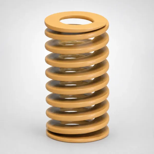
Return and spring rating. Gear molds run with tight ejection and often with slides or lifters for undercut hubs. Return springs must be rated for the full stroke plus 10 % preload, and guided ejection plates are mandatory when more than four pins act on a ring. Unguided ejection on a gear tool bends the plate by 0.02 mm and creates the very runout the cavity was built to avoid.
Ejector pin steel choice follows the same logic as the cavity. SKD61 pins nitrided to HV 900 to 1,100 resist wear against glass-filled gear resins, while standard H13 pins wear 0.02 mm in 200,000 cycles and start marking the web. The cost difference per pin is small compared with one scrapped gear batch.
Gear Inspection: Profile, Helix and Runout on a CMM
A gear cavity is only as good as the parts it proves, so the inspection plan has to name features, instruments and frequencies before the first shot. A gear measuring center or CMM with a rotary table reports profile deviation, helix deviation and runout in one setup. A standard CMM without a rotary axis can still measure runout and tooth thickness, but not helix.
Report against a named standard. State the AGMA 2015-1-A01 grade or the ISO 1328-1 grade on the drawing, then list the tolerance values that grade implies at the actual pitch diameter. A grade with no numeric values is not an acceptance criterion. This is the same discipline that governs how a mold buyer reads any dimensional report, and the CMM report guide for mold buyers walks through the columns and symbols.
| Feature | Symbol | Typical target | Instrument | Frequency |
|---|---|---|---|---|
| Profile deviation | f_fα | ≤0.010 mm | Gear measuring center | First article and every 50k shots |
| Helix deviation | F_β | ≤0.012 mm | Gear measuring center | First article and tool service |
| Single pitch deviation | f_pt | ≤0.008 mm | Gear measuring center | First article |
| Total runout | F_r | ≤0.025 mm | CMM with rotary table | Every 20k shots |
| Tooth thickness | s_n | ±0.030 mm | CMM or span gauge | Every 20k shots |
| Bore to pitch diameter | Coax | ≤0.010 mm | CMM | First article |
← swipe to scroll →
Table note: Typical figures for molded gears of 1 to 2 module in POM and PPS. Targets must be confirmed against the AGMA or ISO 1328-1 grade called out on the customer drawing.
Inspection timing changes the result. Measure after 24 to 48 hours of conditioning, at 23 °C, with the parts dry for PA grades. A runout reading taken 30 minutes after ejection can be 0.010 mm worse than the stable value, purely from thermal contraction. Reading early forces an unnecessary cavity correction that later shows as an oversized tooth.
Sample size drives confidence. Take 5 parts from every cavity at first article, then 3 parts per cavity per shift during ramp. With 8 cavities and a 0.010 mm runout spread, a single-part check has roughly a 1 in 4 chance of missing the worst cavity. Track per-cavity data to a chart, not a single value.
Functional backup. Dimensional data does not cover noise or wear. Run a paired test with the mating gear at the rated torque for 50 hours and check the wear pattern on the flanks. A gear inside every tolerance but with a 0.02 mm lead error will show a bright band across the flank within 10 hours.
The mold-side proof. Before the mold leaves the shop, measure the cavity itself. Record cavity bore position, tooth ring circularity and tooth space index on the assembled plate. Those numbers predict the part runout within 0.005 mm and give the maintenance team a baseline for every future service.
Gear Mold Tool Life and Maintenance
A gear mold holds accuracy only while its tooth ring holds geometry, and the ring wears fastest where the melt scours the gate and where glass fibers slide on the flank. Unfilled POM at 500,000 shots typically wears the ring by 0.010 to 0.020 mm, which is worth about one AGMA grade. Glass-filled PPS at 200,000 shots can wear the same ring by 0.03 mm.
Cavity steel at HRC 62 with a nitrided or PVD-coated flank is the baseline for filled resins. An uncoated ring at 48 to 52 HRC will polish out the gate area first and start to show gate blush at 100,000 shots. Coating cost is 3 to 6 % of the insert price and typically doubles the interval between ring services.
Set inspection intervals from shot count, not from complaints. A practical schedule for a 4-cavity gear tool: every 50,000 shots check tooth thickness and runout on 3 parts per cavity, every 200,000 shots pull the cavity plate and check runout on the assembled ring, and every 500,000 shots remove and re-measure the tooth ring on the CMM.
Most gear rings can be recovered rather than replaced. A uniform wear pattern of 0.02 to 0.05 mm on the flank is corrected by a wire EDM skim pass with the ring removed from the plate and re-set on the same datum. Expect 1 to 2 days of shop time and 15 to 25 % of the original insert cost. Replacement costs 4 to 6 times that figure and adds 2 to 3 weeks of lead time.
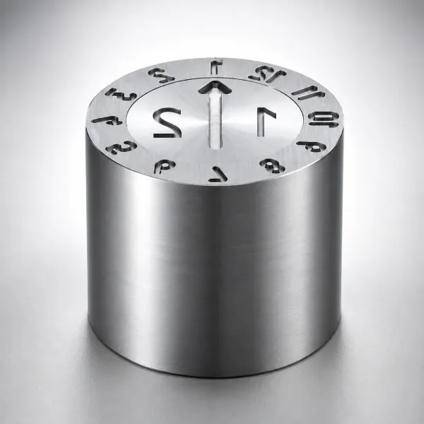
Spares that pay for themselves. Keep one complete tooth ring insert per cavity geometry, one set of ejector sleeves and two ejector plates in stock. Standard components such as ejector pins, core pins, sprue bushings, guide pins and springs ship in 3 to 7 days, so the long-lead risk sits with the custom ring only. A ring on the shelf removes 2 to 3 weeks from any unplanned stoppage.
Storage between runs. A gear ring with sharp tooth edges rusts at the root fillet first, and 0.005 mm of corrosion reads as a profile defect on the next batch. Coat the cavity with a rust inhibitor, bag the plate with a desiccant, and store it flat. Verify runout at the start of every production campaign, not only after a service.
DFM Checklist for Gear Mold Projects
Send the gear drawing and the mating gear drawing together, not the part alone. Accuracy grade, backlash, datum scheme and operating temperature belong in the same package, because each one changes the cavity correction. An IATF 16949 mold shop with 120+ machines will return a DFM review in 24 hours that flags the geometry risks before steel is ordered.
Confirm eight items before cutting: the named accuracy standard and grade with numeric tolerances, the pitch diameter and module with tolerance, the shrinkage factors radial and tangential plus the grade data sheet, the gate type and position with the weld line location, the cavity count and layout with the datum, the ejection method with contact areas, the cooling layout with the expected cavity temperature, and the inspection plan with instrument and frequency.
Then agree the acceptance rule. A first article is accepted when every feature in the inspection plan passes on 5 parts from every cavity, with the CMM report traceable to the drawing. Tool capacity for a gear mold runs 2 to 5 weeks from design freeze, and the DFM review should add no more than one day to that schedule.
Most gear tool failures trace back to one of three gaps in the package: an accuracy grade with no numeric tolerance, a single shrinkage factor applied to an anisotropic ring, or a runout callout with no datum. Closing those three gaps at the quote stage removes the largest single source of schedule risk in a gear mold project.
FAQ
Q1. What shrinkage should I give a mold maker for a POM gear?
Give the grade data sheet, not a single number. Unfilled POM homopolymer runs 1.8 to 2.2 % and copolymer 1.6 to 2.0 %, and the radial factor is 0.95 to 1.00 of the tangential value. Also state whether the part will be measured dry or conditioned.
Q2. Can a molded plastic gear really hold AGMA 10?
Yes, with limits. A gear under 30 mm pitch diameter in unfilled POM, moulded in a 2 or 4 cavity three-plate tool with a center pin gate, can hold AGMA 9 to 10 on profile and runout. Above 60 mm diameter, warpage and cooling asymmetry usually cap the practical grade at AGMA 8.
Q3. How many cavities should a precision gear mold have?
Two for the tightest classes, four when the cavity plate can be machined in one setup against a shared datum, and eight or more only with a hot runner and per-cavity correction. Each additional nozzle drop adds 0.010 to 0.020 mm of cavity position error.
Q4. Why does my gear runout change between production runs?
Usually thermal or wear related. A cavity temperature shift of 5 to 10 °C changes shrink enough to move runout by 0.008 mm, and 500,000 shots of glass-filled resin wears the ring by 0.02 to 0.03 mm. Check the water circuit and the ring geometry before adjusting process settings.
Q5. How do I verify a gear cavity before accepting the mold?
Ask for cavity-level data on the assembled plate: bore position, ring circularity and tooth index, all measured against one datum. Those numbers predict part runout within 0.005 mm and become the maintenance baseline for the life of the tool.
The Bottom Line
Precision gear molds live or die on three numbers: cavity concentricity inside 0.010 mm, two-direction shrinkage correction across a 1.4 to 2.0 % band, and runout held under 0.025 mm through the life of the ring. Fix those in design and the tool ships on a 2 to 5 week schedule with an inspection report that matches the drawing. Talk to DieStrike about your gear tooling through our contact page.
KEEP READING
Related Reading
5 Shrinkage Compensation Rules for Mold Design
How to convert material shrinkage data into cavity steel dimensions without chasing the first trial.
Read articleArticleHow to Design Molds for Automotive Connectors
Connector tooling rules for thin walls, tight pin positions and high-cavity hot runners.
Read articleArticleHow to Maintain a Mold: Weekly/Monthly/Annual Schedule
A preventive schedule that keeps tooth rings, cores and ejectors inside tolerance.
Read articleServiceInjection Mold Manufacturing
Precision gear and transmission molds built to ±0.005 mm with IATF 16949 process control.
Read articleNEXT STEP
Ready to Start Your Mold?
Send us your element dimensions or part numbers — our team responds within 24 hours with pricing and lead time.

Written by
Ray ChanMold Buyer's Guide Author · Precision Mold Manufacturing Specialist. Ray helps global importers, distributors and OEMs source factory-direct molds and mold parts.