
How to Design Molds for Rubber Injection Molding
Table of Contents
A 12 cavity EPDM cold runner tool was released with its cold runner block set to 95 °C instead of 70 °C. The runner gelled on the fourth shot, the needles stalled against cured rubber, and the tool came off the press for a three day teardown. That same tool flashed a 0.15 mm fin along the parting line in the same week. Both the cure balance and the shut-off clearance had to be rebuilt before the first order shipped.
Rubber is a thermoset. It arrives at the cavity uncured, and the mold has to deliver enough heat to finish the reaction inside the cavity. A plastic tool removes heat from a melt that is already fluid. A rubber tool adds heat to a compound that is stiff, sticky and 0.15 to 0.30 W/m·K in thermal conductivity.
That inversion drives every decision in this guide: cold runner architecture, thermal separation, shrinkage compensation, vent depth, parting-line sealing, soft-part ejection, steel and coating choice, and cure time. Material grades and cure chemistry belong to the LSR material guide. Every number below is a typical industry value or a plant capability figure, so confirm it against the compound datasheet and the heat treatment certificate before a drawing is released.
The Snapshot
- 130 to 180 °C of thermal separation. The cold runner block and the barrel hold 60 to 90 °C while the cavity runs 160 to 200 °C. Insulating plates of 8 to 12 mm keep the two halves apart in one stack.
- 1.5 to 4 percent shrinkage, by compound. NBR lands near 1.5 to 2.5 percent, EPDM at 2 to 3.5 percent and FKM at 2.5 to 4 percent. Cut the cavity oversize from a measured curve, not a handbook average.
- Vent depth of 0.002 to 0.005 mm. Deeper turns the vent into a flash channel at 100 to 200 MPa of injection pressure. Shallower traps gas and burns the part at 180 °C.
- Steel at HRC 48 to 52 with a release surface. Flash zones take hard chrome at 0.02 to 0.05 mm or a PTFE layer. Uncoated soft steel grabs a 0.02 mm film of rubber within 5,000 shots.
Why Rubber Injection Tooling Differs
Three physical properties separate a rubber tool from a plastic tool. The first is viscosity. A rubber compound is delivered as a strip or a granule and plasticized by a short screw at 60 to 90 °C. It leaves the barrel at a Mooney viscosity of 30 to 80 MU. That is why injection pressure runs 100 to 200 MPa, against 60 to 120 MPa for a glass-filled engineering resin.
The second is thermal conductivity. Rubber sits at 0.15 to 0.30 W/m·K, roughly one hundredth of tool steel. Heat has to travel from the hot cavity wall into the part, so cure time grows with wall thickness squared rather than linearly.
The third is the absence of a melt history that can be reversed. A thermoplastic part that is short or warped can be reground and rerun. A rubber part that is undercured is scrap, because cure is a chemical reaction and the reaction stops where the heat stopped.

Clamp force follows the same logic as the pressure. A rubber tool needs less clamp tonnage than a plastic tool, but the clamp must be mechanically even. A platen tilt of 0.02 mm across a 400 mm tool opens a flash path at one end of the parting line.
Cold Runner Block Against a Hot Cavity
The cold runner block is the defining feature of a rubber injection tool. It carries the plasticized compound from the barrel to the gate while keeping it below the scorch threshold, at 60 to 90 °C, against a cavity that runs 160 to 200 °C. The gap between the two zones is 90 to 130 °C inside one stack of plates. The architecture mirrors the cold deck used in LSR tools, with a wider temperature band because the compound is far stiffer.
Insulating plates are the first line of defence. Glass-filled PTFE, PEEK or polyimide sheet of 8 to 12 mm thickness carries 0.25 to 0.5 W/m·K against 25 to 45 W/m·K for tool steel. That ratio is what makes the architecture work. The plates also carry the full clamp load, so they are sized like a steel plate and replaced on a schedule.
Give the cold runner block its own temperature controller at ±1 °C, and never tap it off the cavity loop. A shared circuit is the most common cause of a runner that gels during a 20 minute stoppage. The cavity side runs its own loop at 160 to 200 °C, sized for even heat across the face rather than for fast cooling.
Runner channels are round and generously sized, typically 4 to 8 mm in diameter for a 4 to 16 cavity layout. Rubber compounds flow badly through sharp direction changes, so every bend needs a radius of at least one channel diameter. Needle shut-off gates are standard above 8 cavities. A needle of 2 to 4 mm closes on a lapped seat and leaves a gate mark of 0.3 to 0.8 mm.
A cold runner block adds 15 to 25 percent to the tool cost and 5 to 8 days to the build. It pays that back within a month, because a conventional runner in a thermoset tool is cured scrap with no regrind path. On a 12 cavity gasket tool the runner can consume 20 to 35 percent of the compound.
Shrinkage by Compound: 1.5 to 4 Percent
Shrinkage in a rubber tool is not a single number. It depends on the compound, the cure temperature, the injection pressure and whether the part is post-cured. NBR lands near 1.5 to 2.5 percent, EPDM at 2 to 3.5 percent, FKM at 2.5 to 4 percent, and a high-consistency silicone can move 3 to 4.5 percent.
The direction of the error matters as much as the size. A cavity cut 0.2 mm too small can be re-cut. A cavity cut oversize has to be welded and re-machined, which adds 5 to 10 days to the lead time. When the curve is uncertain, cut small and leave 0.1 to 0.3 mm of stock on the dimension that will move.
| Compound | Typical shrinkage | Cure temperature | Cavity size on a 50 mm dimension |
|---|---|---|---|
| NBR, nitrile | 1.5 to 2.5 percent | 150 to 180 °C | 50.76 to 51.28 mm |
| EPDM | 2 to 3.5 percent | 160 to 190 °C | 51.02 to 51.81 mm |
| FKM, fluoroelastomer | 2.5 to 4 percent | 170 to 190 °C | 51.28 to 52.08 mm |
| Silicone, high consistency | 3 to 4.5 percent | 160 to 190 °C | 51.55 to 52.36 mm |
← swipe to scroll →
Table note: shrinkage bands are typical values for injection-molded thermoset rubber and move with cure temperature, filler loading and post-cure. Measure the curve on the production compound with a 4 cavity trial tool before any multi-cavity cavity is cut.
Two process effects are large enough to change a cavity dimension. Raising the cure temperature by 10 °C typically adds 0.2 to 0.4 percent of extra shrinkage. Post-curing a FKM part at 200 to 250 °C for 4 to 24 hours adds another 0.2 to 0.5 percent, so the post-cure question belongs in the DFM review.
Compensate the flash face and the seal faces in the same pass. A cavity cut oversize with mating blocks left at nominal changes the shut-off clearance by 0.03 to 0.10 mm, which turns a working tool into a flashing one.
Degassing and Vent Depth at 0.002 to 0.005 mm
Rubber releases gas during cure. Moisture on the compound, volatile process aids and the cure by-products themselves all have to leave a cavity that is 160 to 200 °C hot and only partly filled. Gas that cannot leave becomes a blister of 0.5 to 2 mm or a burnt patch on the surface.
Vent depth for a thermoset rubber tool runs 0.002 to 0.005 mm at the cavity land. The land itself runs 2 to 4 mm long, then a relief channel of 0.5 to 1 mm carries the gas to atmosphere. Never open the cavity edge vent past 0.005 mm. At 100 to 200 MPa of injection pressure a compound at 30 to 80 MU fills a 0.01 mm channel and leaves a hair fin along the whole vent line.
Locate vents at the last point to fill and at every gas trap: the far wall of a ring, the base of a deep pocket, the end of a long rib. On a boot or a closed-end diaphragm, add a vent at the top of the core and an overflow pocket of 0.2 to 0.5 cm³ that takes the cold slug and the trapped air.

Above 8 cavities, or on any part with a wall under 1.5 mm, add vacuum assist. Pulling the cavity to 0.05 to 0.10 bar absolute before injection removes most of the air and lets the vent land stay at the low end of the range. On seals of 0.5 to 5 g, vacuum plus a 2 to 4 second evacuation often decides whether the blister rate is 6 percent or 0.8 percent.
Clean vents on a shot count, not on a reaction. Rubber leaves a cured film that closes a 0.003 mm channel after 2,000 to 5,000 shots. Put the check in the maintenance plan with a 0.002 to 0.005 mm feeler gauge and a light pass on a surface plate.
Flash Control at the Parting Line
Flash decides whether a rubber program is profitable. A part that leaves the press with a 0.15 mm fin needs 60 to 120 seconds of manual trimming. On a 30 shot per minute tool that costs more labour than the molding. Trim dies or cryogenic tumbling at minus 80 to minus 120 °C can deflash a part, but only if the fin is thin and uniform.
Set the shut-off clearance at 0.01 to 0.02 mm on every parting-line land, with a land width of 5 to 10 mm. That band is wider than an LSR tool needs, because a compound at 30 to 80 MU does not pass a 0.01 mm gap under normal pressure. It is tight enough that a worn land shows up as flash before it shows up as a dimension.
Land width is the wear budget. A 3 mm land has taken 2,000 full-tonnage clamping cycles by the time the tool reaches 2,000 shots. A 5 to 10 mm land spreads that load and holds flatness for 300,000 to 500,000 shots in a hardened insert.
Vertical shut-offs need 3 to 5 degrees of draft or a matched taper. Two parallel vertical walls flash as soon as the blocks reach 160 to 200 °C and grow by 0.03 to 0.08 mm. The same rule applies to core-to-cavity seals on a boot or a bellow, where the wall is 1 to 2 mm and the flash path is short.
Three habits destroy these numbers. The first is stoning a land by hand, which opens the clearance by 0.005 to 0.01 mm in a few strokes. The second is shimming a low land instead of re-cutting it. The third is cutting the seal into a pre-hardened plate at HRC 30, where the land peens after 100,000 to 200,000 shots.
Ejecting Soft Parts: Pads, Air Assist, No Thin Pins
A rubber part at 40 to 80 Shore A does not need force to remove. It needs area and direction. A point load from a 2 mm pin pulls a 1.5 mm wall into a cone and tears it. The tear leaves a 0.3 mm witness mark on a part where no mark is allowed.
Use the largest contact area the geometry allows. A stripper plate on the full perimeter is the first choice for gaskets and flat seals, with 20 to 40 mm of travel to clear the core. Flat pads of 20 to 40 mm handle domed parts. Air assist through the core at 0.3 to 0.6 MPa for 0.5 to 2.0 seconds breaks the bond without touching the part.

Where pins are unavoidable, keep them flat ended, put them on hidden faces and hold the diameter at 3 mm or more. Rubber at 40 to 80 Shore A with a tensile strength of 8 to 25 MPa stretches before it releases. A 3 mm flat pin spreads the load over 7 mm², which keeps the local pressure inside what the compound tolerates.
Eject hot, not cold. A rubber part is most elastic at 160 to 180 °C and releases cleanly. Let it sit for 10 seconds and it cools toward 80 °C, stiffens and grips harder. Time the cycle so the knock-out starts within 1 to 3 seconds of mold opening.
Draft carries more weight here than in a plastic tool. Use 1 to 3 degrees on walls and 3 to 5 degrees on deep cores and ribs. A 0.5 degree draft that works in polypropylene drags and scuffs in an EPDM part, because elastic recovery pulls the compound back against the steel.
Steel and Coating Choice Against Sticking
The cavity spends its whole life at 160 to 200 °C, and a 12 cavity tool running 30 shots per minute takes 300,000 to 600,000 shots in a year of two-shift production. Steel has to hold the flash land flat for that count, and the surface has to release a cured compound.
Through-hardened chromium hot-work steel in the 1.2343 or 1.2344 family at HRC 48 to 52 is the default for cavity inserts and flash lands. A wear land that carries the full flash load can go to HRC 62. Where the compound uses an acidic cure system, or the part must stay white, stainless mold steel in the 1.2083 family takes the same hardness. It resists residue better at the cost of 5 to 10 percent slower heat-up.
| Surface or steel | Hardness or thickness | Where it belongs | Failure it prevents |
|---|---|---|---|
| 1.2343 or 1.2344 steel | HRC 48 to 52 | Cavity inserts, flash lands, core pins | Land peening that opens a 0.01 to 0.02 mm seal |
| 1.2083 stainless | HRC 48 to 52 | Medical, white and acidic-cure compounds | Corrosion pitting and surface staining |
| Hard chrome plating | 0.02 to 0.05 mm | Flash zones, gates, core pins | Rubber pick-up and sticking at the vent land |
| PTFE release layer | 5 to 20 µm | Ejection faces and deep cores | Tearing on the first pull from a deep core |
| Nitriding | 0.10 to 0.30 mm case at 900 to 1100 HV | Wear lands, guide bores, slides | Abrasive filler wear on mineral loaded stocks |
| DLC coating | 1 to 3 µm | Ejector pads, sleeves, hard-to-release cores | Sliding friction and adhesive wear at 0.02 mm contacts |
← swipe to scroll →
Table note: hardness bands and coating thicknesses are typical industry values. Confirm the heat treatment certificate, the plating thickness report and the coating adhesion test before assembly, and file all three in the tool record.

Coating is a release decision before it is a wear decision. A part that grabs a polished core tears on ejection no matter how the stroke is timed, and hard chrome at 0.02 to 0.05 mm solves most of those cases. PTFE at 5 to 20 µm gives lower friction and suits a deep core, but it wears faster and needs re-application at 150,000 to 300,000 shots. Never spray a release agent into the cavity to cover a geometry error, because the film migrates into the part and changes bonding.
Buy mold steel through the same IATF 16949 mold manufacturing channel that cuts it. A heat treatment certificate and a hardness map on the finished insert are the two documents that decide whether a flash land holds 0.01 to 0.02 mm for 500,000 shots or opens after 100,000.
Cure Time and Cycle Design
Cure time is a thermal calculation, not a press setting. Heat enters through the cavity wall, so the thickest section controls the cycle. At 175 to 185 °C, allow 60 to 90 seconds for a 2 mm wall, 2 to 3 minutes for 4 mm and 4 to 8 minutes for 6 mm in an EPDM or NBR compound.
FKM needs longer, typically 2 to 4 minutes at 3 mm and 170 to 190 °C, plus a post-cure of 4 to 24 hours at 200 to 250 °C. Sulfur-cured compounds run cooler at 150 to 170 °C and cure in 2 to 6 minutes. Peroxide-cured compounds run at 170 to 190 °C and need a more even cavity face.
Cavity temperature uniformity is worth ±3 °C across the face. A 5 to 10 °C spread between the center and the outer cavities changes cure time by 15 to 30 percent. It shows up as a 0.1 to 0.3 mm dimensional spread plus a 2 to 5 point hardness difference. Verify the profile at six points before any capability run.
Size cooling for the heat that has to leave the mold, not for a fast freeze. A 4 cavity tool holding 180 °C with a 6 mm part puts 8 to 20 kW into the steel. Use 10 to 12 mm gun-drilled channels at 15 to 25 mm from the cavity surface and keep the flow turbulent at 4 to 8 L/min per circuit.
Build the cycle from its parts. Injection takes 3 to 10 seconds at 100 to 200 MPa, cure takes what the wall thickness sets, and opening, ejection and part removal take 10 to 20 seconds. A 4 mm part lands at 3 to 4 minutes, so 2,000 first-article shots take 4 to 6 days of single-shift running.
Failure Modes: Torn Parts, Undercure and Trapped Gas
Four failure modes account for most of the scrap in a rubber tool, and each one has a different root cause. Reading the defect correctly saves 1 to 3 days of trial time, because the fix sits in the tool or the cycle, never in a random adjustment.
Torn parts and backrinding. A tear in the body points to a point load on ejection, no draft or a core that grips. Backrinding is different: the cavity pressure releases before the network sets, the compound pulls back from the parting line and the edge comes out rough and chewed. Fix it by holding the clamp until the compound sets, or by adding a 0.05 to 0.10 mm pre-cure hold. Backrinding on 10 to 30 percent of parts usually means the cavity is 10 to 20 °C below setpoint.
Undercure. An undercured part comes out tacky, smears on the steel and blisters when post-cured. It measures 3 to 8 Shore A below target hardness and shows a compression set 20 to 40 percent worse than specification after 70 hours at 100 °C. A part can look perfect at inspection and still fail that test, which is why the cure check belongs on the trial sheet.
Trapped gas. Blisters of 0.5 to 2 mm and brown surface patches point at vents, not at the compound. Check the vent land with a feeler gauge, count shots since the last cleaning, and confirm the evacuation time if the tool runs vacuum. On a wall under 1.5 mm, a 2 to 4 second evacuation at 0.05 to 0.10 bar absolute removes the air before the shot.
Scorch in the runner. A compound that cures in the cold runner shows up as short shots, hard particles in the part or a needle that will not close. Mooney scorch time is typically 5 to 15 minutes at 120 °C, so a runner held above 90 °C for 20 minutes is already outside its window. Keep the block at 60 to 90 °C and never leave material idle in it during a break.
Tool Life and Maintenance Intervals
A well-built rubber tool runs 500,000 to 1,000,000 shots before the cavity inserts need rework. That number holds only if flash lands, vents and coatings are maintained on a schedule. Each of those features fails gradually and shows up as scrap before it shows up as a dimension.
Set the intervals by shot count and write them into the tool file. Vents at 2,000 to 5,000 shots. Flash lands inspected and polished at 50,000. Release coatings re-applied at 150,000 to 300,000. A teardown with land re-cutting at 500,000, and insert refurbishment at 1,000,000 shots.
Keep a consumable list with the tool. Needles and seats, ejector pads, springs, guide bushings and insulating plates are all wear items, and standard components ship in 3 to 7 days from the catalog. A tool waiting 2 weeks for a custom needle has lost more than the spare would have cost.
Storage matters more than most shops expect. Keep the tool between 20 and 30 °C, out of direct sunlight and off a concrete floor, with the blocks ajar on a stand so the insulating plates are not under load. A tool stored closed at 40 °C can take a permanent set in the plate stack within one season.
Tolerances, Inspection and Trial Acceptance
Mold geometry on a rubber tool holds ±0.005 mm on the critical seal and shut-off features, and ±0.002 mm on interchangeable inserts and components. The cavity dimension is then set from the measured shrinkage curve, so a drawing that fixes the cavity itself usually describes a number that changes after T1.
Part tolerances follow the compound rather than the tool. A typical drawing lands on an ISO 3302-1 class M2 or M3 band, where a 10 mm dimension sits near ±0.10 to ±0.15 mm and a 50 mm dimension sits near ±0.25 to ±0.40 mm. Tighter bands are possible on fixed geometry with a stable compound, but they need a capability run of 30 to 50 shots per cavity.
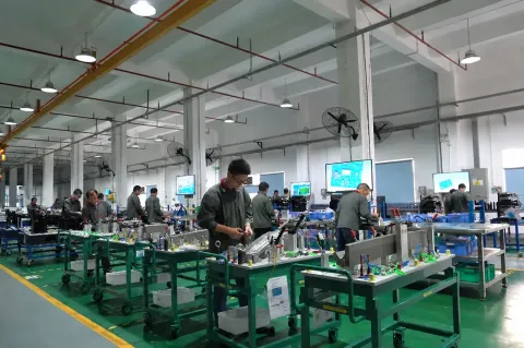
Run the trial in the same order every time. Approve the steel with a CMM report on the cavity and the flash lands before assembly. Verify the thermal profile at six points. Run T0 on a short shot and a full shot to confirm needle timing, gate shear and venting, then T1 for dimensional data over 30 to 50 shots per cavity. Only then does a capability study make sense.
Write the acceptance criteria into the purchase order so both sides measure the same thing. Gate mark under 0.8 mm. No flash above the drawing limit at any parting line or vent. Cavity face variation within ±3 °C, a cured surface free of tack after 24 hours, and a compression set result inside specification. Add the tool life assumption and the shot count for coating or land rework.
DFM feedback takes 24 hours, mold lead times run 2 to 5 weeks, and standard components ship in 3 to 7 days. A program that adds a 4 to 6 day T1 window and a 3 to 5 day capability run should budget 6 to 9 weeks from drawing release to a validated part.
The Bottom Line
A rubber injection tool is won or lost on five numbers. Hold the cold runner block at 60 to 90 °C against a 160 to 200 °C cavity. Compensate the cavity for a measured shrinkage of 1.5 to 4 percent.
Keep the vent land at 0.002 to 0.005 mm. Seal the parting line at 0.01 to 0.02 mm on a 5 to 10 mm land. Harden the flash faces to HRC 48 to 52 with a chrome or PTFE release layer. Get those right and the compound behaves predictably. Miss them and no cycle adjustment recovers the tool.
DieStrike builds rubber, thermoset and precision injection molds to IATF 16949, with 120+ machines and mold accuracy of ±0.005 mm. EDM and jig grinding hold ±0.002 mm, cavity hardening reaches HRC 62, standard components ship in 3 to 7 days and tool lead times run 2 to 5 weeks. Programs here run for the same sealing and connector applications as tier-1 suppliers including TE, Amphenol, Luxshare and Dongshan, where a 0.02 mm flash land is a schedule risk and not a cosmetic detail. Send the part drawing and the compound datasheet and we will return a tooling concept with the cold runner decision spelled out before steel is cut.
KEEP READING
Related Reading
Liquid Silicone Rubber (LSR) Injection Molding Guide
Cold deck architecture, valve gate needles and catalyst poisoning control for a 20 to 30 °C feed system.
Read articleArticleThermoset vs Thermoplastic: Mold Design Impact
Why a curing compound needs a hot cavity and a short runner, and how that reorders the whole tool layout.
Read articleArticleMold Venting: Depth, Location and Design Rules
Vent land depth, relief channels and last-fill placement for compounds that trap gas at low injection speed.
Read articleServiceInjection Mold Manufacturing
IATF 16949 mold building with 120+ machines, mold accuracy of ±0.005 mm and 2 to 5 week lead times.
Read articleNEXT STEP
Ready to Start Your Mold?
Send us your element dimensions or part numbers — our team responds within 24 hours with pricing and lead time.

Written by
Ray ChanMold Buyer's Guide Author · Precision Mold Manufacturing Specialist. Ray helps global importers, distributors and OEMs source factory-direct molds and mold parts.