
How to Design LSR Molds: Cold Deck, Sealing and Tooling
Table of Contents
A 16 cavity LSR valve gate tool came back from the bench with a 0.02 mm shut-off clearance at the parting line. For a polypropylene tool that number is normal. For liquid silicone it is a flashing channel. On the first production run the melt filled the gap and pushed a 0.35 mm fin around three cavities, and the launch slipped nine days while the seal lands were hand-fitted down to 0.004 mm.
Liquid silicone rubber arrives at the cavity at 100 to 1000 Pa·s. It cures by platinum addition in 3 to 30 seconds at 150 to 200 °C. It produces no reusable sprue and no regrind. Those three facts reorder every design priority that a plastic mold shop follows by habit.
This guide covers the mold body: thermal separation, cold deck architecture, valve gate and needle selection, parting-line sealing, venting, steel and coating choice, ejection of soft parts, cleaning and trial acceptance. Resin grades and cure chemistry belong to the LSR material guide. Bonding silicone to a hard substrate belongs to the two-shot mold guide. All figures below are typical published or industry values, and each one needs checking against the steel certificate and the silicone datasheet before a drawing is released.
The Snapshot
- Temperature split of 130 to 180 °C. The barrel and cold runner hold 20 to 30 °C while the cavity runs 150 to 200 °C. Insulating plates of 6 to 10 mm and a separately chilled drop plate maintain that gap.
- Seal at 0.005 mm or flash. LSR at 100 to 1000 Pa·s passes a 0.010 mm steel gap in a single shot. Shut-off lands belong at 0.002 to 0.005 mm with a 3 to 6 mm land width.
- Vent depth of 0.002 to 0.005 mm. Deeper turns the vent into a flash channel. Shallower traps air and burns the part at 150 to 200 °C in under 3 seconds.
- Hardened steel at HRC 48 to 54. Cavity inserts take 500,000 to 1,000,000 shots in silicone. Soft steel wears at the seal lands and the 0.005 mm clearance becomes 0.02 mm.
- Contamination is a cure failure. Sulfur, tin, amine and some release agents deactivate the platinum catalyst, and a part that will not cure cannot be recovered by lengthening the cycle.
Why LSR Breaks Standard Tooling Rules
A thermoplastic tool is designed to remove heat. The melt enters at 230 to 300 °C, the steel sits at 60 to 90 °C, and the part freezes in 8 to 30 seconds because the wall is thin and the conductivity is high. Every cooling decision in that tool points in one direction.
A silicone tool runs the other way. The metal has to deliver heat into the cavity and hold it there. The part leaves the mold already cured, at 150 to 200 °C, and it stays flexible from 40 Shore A up to 70 Shore A. There is no frozen skin to protect the geometry and no pressure to hold the part on the core.

The second break is pressure. A glass-filled engineering resin needs 60 to 120 MPa to fill a long flow path. LSR typically needs 5 to 15 MPa because the viscosity is low and the wall sections are often 0.5 to 3 mm. Low pressure means low clamp force, so a 16 cavity silicone tool can run on a machine that a comparable plastic tool would never fit. It also means gravity, vent depth and shut-off clearance control the fill, not clamp tonnage.
The third break is shear and history. Silicone in the feed system must stay below the cure threshold. A local shear heating spike of 10 °C at a gate, or a runner sitting at 45 °C for 25 minutes during a stoppage, is enough to start cure inside the tool. Once the runner gels, the mold comes off the press and strips to bare plates.
Treat the tool as two machines bolted together. One is a refrigerated feed system that must never warm up. The other is a heated cavity that must never cool down. Design them as separate systems and the LSR process becomes predictable.
Thermal Separation: Cold Deck, Insulating Plates and Cooling
A cold deck carries the mixed A and B components from the metering unit to the gate without letting the material cross the cure threshold. Two temperatures sit 130 to 180 °C apart inside one stack of plates, and the only thing keeping them apart is insulation and a controlled cooling circuit.
Insulating plates are the first line. Glass-filled PTFE, PEEK or polyimide sheet at 6 to 10 mm thickness carries a thermal conductivity of roughly 0.25 to 0.5 W/m·K against 25 to 45 W/m·K for tool steel. That ratio is what makes the whole architecture possible. The plates must be sized for the full clamp load of the tool, because they see the same compression as a steel plate once the press closes.
The cold runner plate runs on its own circuit at 15 to 25 °C, ideally on a separate temperature controller with ±1 °C control. Do not tap that circuit off the cavity loop. A shared loop is the most common reason a silicone tool gels a runner during a lunch break. The cavity side runs its own circuit at 150 to 180 °C, sized for even heat rather than for fast cooling.
| Zone | Typical temperature | Hardware | Failure if wrong |
|---|---|---|---|
| Metering unit and barrel | 20 to 30 °C | A and B pumped separately at a 1:1 ratio | Material cures in the pump, 8 to 12 hours of downtime |
| Cold runner plate | 15 to 25 °C | Tool steel with a dedicated chiller circuit | Runner gels and the tool strips to bare plates |
| Insulating plate | Cold face under 30 °C | Glass-filled PTFE or PEEK, 6 to 10 mm thick | Heat leaks through and the runner gels in 20 to 40 minutes |
| Nozzle drop and needle | 25 to 60 °C | Hardened needle closing on a lapped seat | Gate cures shut or the drop runs cold and short shots |
| Cavity block | 150 to 200 °C | Hardened insert steel at HRC 48 to 54 | Under-cure, a 0.5 to 2 mm sticky skin and tearing on ejection |
| Cavity-side cooling | 150 to 180 °C | 10 to 12 mm gun-drilled channels | Cycle grows from 25 seconds to 60 seconds and cure drifts |
← swipe to scroll →
Table note: temperature bands are typical industry values for addition-cure LSR on a cold deck tool. Confirm against the silicone datasheet and the controller setpoints recorded during the trial.
Cooling on the cavity side is a heater safety net, not a fast-freeze circuit. Its job is to trim the block back to setpoint when shear or cure exotherm pushes it 5 to 10 °C high. A tool that cannot hold ±3 °C across the cavity face will produce parts with a 0.1 to 0.3 mm cure gradient and visible tearing on the hot cavities.
Cold Runner and Valve Gate Design
Runner channels in a cold deck are round, fully radiused and generously sized. Typical diameters run 3 to 6 mm depending on the drop count, and every direction change carries a radius of at least one channel diameter. Sharp corners cost pressure and add shear. Square corners also create dead zones that hold a slug of material through a shift.
Valve gates are the standard choice above 8 cavities. A needle closes against a hardened, lapped seat and gives a clean gate mark of 0.2 to 0.5 mm. Needle diameter typically runs 1.5 to 3 mm with 0.5 to 1.5 mm of travel, driven pneumatically at 4 to 6 bar or hydraulically on larger tools. The seat is where the design is won or lost: it must seal without marking the part and it must shear the cured silicone at the gate each cycle.

Sequence the needles to balance fill. Silicone at 100 to 1000 Pa·s moves quickly once the gate opens, so a 0.3 second stagger between drops changes which cavity fills last. On a 16 drop tool, opening the outer drops first by 0.2 to 0.4 seconds is often enough to remove a pressure imbalance that would otherwise show as a 0.15 mm dimensional spread across the cavity set.
Avoid shear at the gate above all else. A gate land of 0.8 to 1.5 mm is long enough to control the fill and short enough to limit local shear heating to a few degrees. Shear heating of more than 10 °C inside the drop is the most common reason a tool that runs clean at 40 shots per minute starts to cure at the gate when the rate rises.
Open pin-point gates remain valid for small parts below 4 cavities. They cost less and give a smaller vestige of 0.1 to 0.2 mm, but they cannot be shut off, so a cold slug can pass into the cavity at the start of each shot. On a 0.3 g septum that slug is a visible defect. On a 20 g gasket it seldom matters.
Parting-Line Sealing and Shut-Off Clearance
Sealing is the design decision that separates a working LSR tool from a scrapped one. Silicone at 100 to 1000 Pa·s behaves like a light oil under pressure. Any steel gap of 0.010 mm or more becomes a flash path, because there is no frozen skin to plug it.
Specify shut-off clearance at 0.002 to 0.005 mm on all parting-line seal lands, with a land width of 3 to 6 mm so the land stays flat after 500,000 shots. Vertical shut-offs need a 3 to 5 degree draft or a matched taper so the block closes on a wedge rather than on two parallel walls. Any parallel vertical wall in a silicone tool will flash once the blocks warm to 150 to 200 °C and move by 0.02 to 0.05 mm.
Three shop habits wreck these numbers. The first is lapping a seal land by hand with a stone, which rounds the edge and opens the clearance by 0.005 mm in a few strokes. The second is shimming a low land instead of re-cutting it, which creates a 0.02 mm step that silicone fills. The third is designing the seal into a soft pre-hardened plate at HRC 30, where seal lands peen over after 200,000 shots and the gap widens on its own.
Put seal lands in hardened inserts at HRC 50 to 54 and grind them. Then map the flash path before the tool is built. On a tool that flashes, the fin thickness tells you the gap: a 0.05 mm fin points to a 0.015 mm clearance, and a 0.3 mm fin points to a shut-off that never closed at all.
Venting LSR Molds: Depth, Location and Vacuum Assist
Silicone tools trap air for a simple reason. Injection pressure runs 5 to 15 MPa instead of 60 to 120 MPa, so the melt has less force available to push gas out of a corner. Air that stays behind a boss or in a last-fill corner reaches 200 °C and burns, and the burn shows as a black or brown patch on a white part.
Vent depth for LSR runs 0.002 to 0.005 mm with a land length of 2 to 4 mm, then a relief channel of 0.5 to 1 mm to atmosphere. Never go deeper than 0.005 mm at the cavity edge. Silicone at 100 to 1000 Pa·s will fill a 0.01 mm vent and leave a hair fin along the whole vent line.
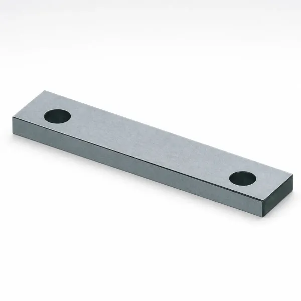
Locate vents at the last point to fill, not at the conventional plastic-tool locations. On a round gasket that is the far side of the ring. On a housing it is the deepest pocket or the far wall behind a core. Flow analysis usually flags these points within 5 percent of the real position, and the trial confirms the rest.
Above 8 cavities or on a wall thinner than 1 mm, add vacuum assist. A sealed tool at 0.05 to 0.10 bar absolute removes the gas before the shot and lets vent depth stay at the low end of the range. Vacuum also helps the melt wet fine features, and on micromolded parts of 0.05 to 0.5 g it is often the difference between a 4 percent reject rate and a 0.5 percent one.
Clean vents every run. Silicone leaves a thin film that closes a 0.003 mm channel after 2,000 to 5,000 shots. A vent that measured correctly at the trial can be sealed shut by the end of the first week, and the burn marks return without any change in the process settings.
Steel and Coating Selection for Silicone Tools
Two forces drive steel choice in an LSR tool: heat, and the fact that silicone is a poor lubricant. Cavity steel sits at 150 to 200 °C for its whole life, and a 16 cavity tool running 40 shots per minute will take 500,000 to 1,000,000 shots in a year of two-shift production.
Stainless mold steel in the 1.2083 family is the default for medical, cleanroom and white-part tools. It resists the acidic and chloride residues that show up in cleanroom washdown, and it takes a polish fine enough for a translucent part. Heat-treated to HRC 50 to 54, it holds a 0.002 to 0.005 mm seal land for the life of the tool. The trade is a lower thermal conductivity than carbon-based hot-work steel, which adds 3 to 8 seconds to the warm-up and slightly slows the cycle.
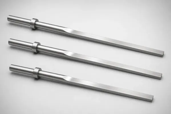
Seal lands, gate seats and core pins take a coating for three reasons: wear, release and clearance stability. Hard chrome at 0.02 to 0.05 mm is the workhorse. It resists wear, releases silicone well and can be stripped and re-plated. PVD layers of 2 to 5 µm hold a tighter tolerance and give a lower friction coefficient, which matters on a needle that cycles once every 1.5 to 3 seconds. Plan a re-coat at 300,000 to 500,000 shots and put that number in the maintenance schedule.
| Steel or coating | Hardness or thickness | Where it belongs | Notes and risks |
|---|---|---|---|
| Stainless 1.2083 (S136) | HRC 50 to 54 | Cavity inserts, medical and cleanroom tools | Corrosion resistant, polishes to Ra 0.05 µm, slower to warm up |
| Hot-work 1.2343 ESR | HRC 48 to 52 | General cavity inserts, high cavity counts | Good thermal conductivity, needs chrome or PVD at seal lands |
| Hot-work 1.2344 (H13) | HRC 48 to 52 | Cold runner plates, drops, needle seats | Tough enough for needle impact, poor corrosion resistance |
| Hard chrome plating | 0.02 to 0.05 mm | Seal lands, gates, core pins | Strip and re-plate at 300,000 to 500,000 shots |
| PVD CrN or TiN | 2 to 5 µm | Gates, needles, tight shut-offs | Low friction, keeps a 0.002 to 0.005 mm clearance stable |
| DLC coating | 1 to 3 µm | Needles, ejector sleeves, filled silicones | Hardest release layer, needs a clean coating process |
| Copper alloy insert | HRC 30 to 40 | Local heat transfer on a slow cycle | Soft, never place it on a shut-off or seal land |
← swipe to scroll →
Table note: grades, hardness bands and coating thicknesses are typical industry values. Confirm the heat treatment certificate and coating thickness report before assembly, and keep both in the tool file.
Platinum Catalyst Poisoning: Sulfur, Tin and Amines
Addition-cure silicone will not cure if the platinum catalyst is deactivated. The part comes out tacky, it smears on the steel, and it cannot be fixed by adding 10 seconds to the cycle or 10 °C to the mold. The cure system is dead, and the fix is a full clean of the tool plus a new material batch.
The main contaminants are sulfur, tin and amines. Sulfur reaches a tool from sulfur-bearing cutting fluids, from vulcanized rubber parts or gloves, and from some workshop dust. Tin compounds come from organotin stabilizers and certain catalysts. Amines arrive in amine-cured epoxy, in some adhesives and tapes, and in amine additives carried over from other resin work on the same machine.
Control the tool, not the part. Keep the LSR tool on a dedicated bench. Use nitrile gloves, never latex or vulcanized rubber. Keep PVC film, tape adhesive and silicone RTV sealant away from the cavity. Clean the tool with isopropyl alcohol and lint-free cloth, and recoat nothing without checking the coating against the material supplier data. If a batch stops curing, log the tool history before cleaning, because the cause is usually traceable to one event in the previous 48 hours.
Also watch the mould release decision. A solvent or silicone release agent can solve a sticky ejection problem and create a cosmetic or biocompatibility problem at the same time. On a medical or optical part, fix the ejection geometry instead of spraying the cavity.
Ejecting Soft Parts: Vacuum Cups and Stripper Plates
A 40 Shore A part does not need much force to remove, but it needs the right direction. Silicone stretches before it releases, so a point load on an ejector pin can pull a 1 mm wall into a 3 mm cone and tear it. The classic defect is a 0.2 mm witness mark on a part where no mark is allowed.
Use the largest contact area available. A stripper plate that pushes on the entire perimeter is the first choice for flat gaskets and seals. Vacuum cups on the moving half, sized 5 to 15 mm across and drawing 0.4 to 0.6 bar, handle thin-walled diaphragms and domed parts. Air assist through the core, at 0.2 to 0.4 MPa for 0.5 to 1.5 seconds, breaks the seal between the silicone and the steel without touching the part.
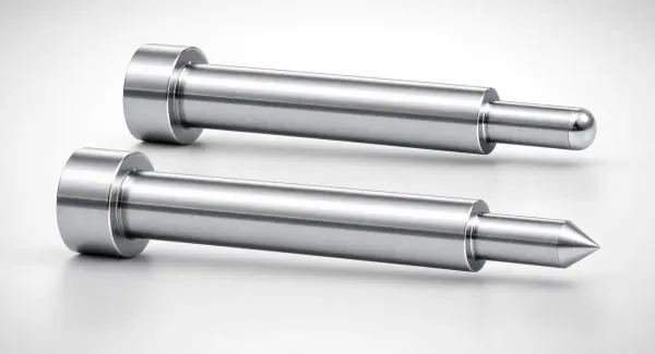
Where pins are unavoidable, keep them off the sealing surfaces. Put them on hidden faces, use flat or slightly crowned ends, and keep the diameter at 1.5 mm or more so the pressure stays under the 1 to 2 MPa that soft silicone tolerates. With LSR tear strength typically in the 10 to 30 kN/m range, a sharp pin edge concentrates stress well past what the material can hold.
Eject at the demolding temperature, not after the tool has cooled. Silicone at 150 to 180 °C is at its most elastic and releases cleanly. Let the part sit 10 seconds and it cools toward 60 °C, stiffens and grips harder. Every tool should be timed so ejection starts within 1 to 3 seconds of mold opening.
Cooling Circuits and Cycle Time in an Insulated Tool
Cooling in an LSR tool has one job: hold the cavity face within ±3 °C of setpoint while the insulated half sits at 20 to 30 °C, 30 mm away in the same stack. That is a heat balance problem, not a heat removal problem.
Gun-drilled channels of 10 to 12 mm at 12 to 20 mm from the cavity surface work for most geometries. Keep the flow turbulent at 4 to 8 L/min per circuit, because a laminar stream in a 12 mm channel carries roughly half the heat per degree that a turbulent one does. Where a core or a deep pocket blocks the path, use baffles or bubblers drilled into the same circuit rather than adding a second loop with its own controller.
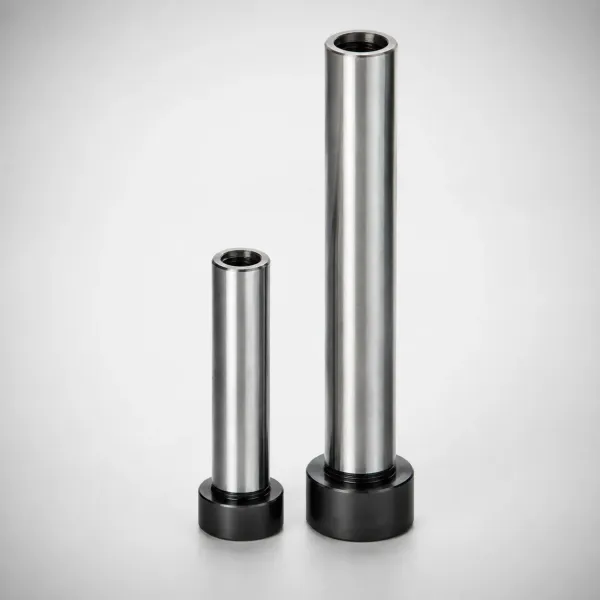
Cycle time follows wall thickness, not cavity count. A 2 mm wall cures in roughly 10 to 15 seconds at 180 °C, and a 4 mm wall takes 25 to 40 seconds at the same setpoint. Lower the cavity temperature to 150 °C and every cure time grows by 40 to 70 percent, so a tool that runs 25 second cycles at 180 °C will run 40 second cycles at 150 °C. Set the cavity to the highest temperature the silicone datasheet allows, then trim for dimensional stability rather than for cycle.
Check the heat balance after warm-up with a surface probe in at least six points across the cavity face. A spread above 5 °C between the center and the outer cavities means the manifold or the platen is bleeding heat into one end of the tool, and the cure will drift on those cavities within the first hour. Fix that before running a capability study, because a temperature-driven cure gradient shows up as a 0.1 to 0.3 mm dimensional shift that no amount of process tuning removes.
Cleaning and Colour Change Between Runs
Cured silicone sticks to steel and to itself. A tool that changes from a black 60 Shore A grade to a translucent 40 Shore A grade needs a full strip, because a single cured speck of the old colour reappears as a dark inclusion in the new part. Plan 4 to 8 hours on a 16 cavity tool and treat it as scheduled downtime, not as a quick wipe.
The sequence that works is mechanical first, chemical second. Open the tool, remove the cold runner plate and the drops, and pull the runner out by hand while it is still warm and elastic. Scrape cured film from seal lands with a brass or plastic tool, never with a steel scraper or a stone. Then clean with isopropyl alcohol and lint-free cloth, and finish with a check under 3x magnification at every vent, gate and shut-off.
Do not run solvent through a 0.003 mm vent and assume it is open. Verify with a 0.002 to 0.005 mm feeler or a light pass on a surface plate. Vents and shut-offs are the two features where a hidden film of silicone causes the next run to fail, and both are invisible until the flash or the burn mark appears 4,000 shots later.
Schedule cleaning by shot count as well as by colour change. Vents at 2,000 to 5,000 shots, seal lands inspected at 50,000, coatings inspected at 300,000 to 500,000, and a full teardown at 1,000,000 shots. Every one of those numbers belongs in the tool file, because the tool that runs three shifts will reach the first interval inside a week.
Tolerances, Inspection and Trial Acceptance
Silicone shrinks 2 to 4 percent and keeps moving after demolding. That changes what a mold tolerance even means. A cavity cut to ±0.02 mm on a part that will shrink 2.5 percent and relax for 24 hours cannot be judged by the cavity dimension alone.
Hold mold geometry at ±0.005 mm on the critical seal and shut-off features, and at ±0.002 mm on interchangeable components and inserts. Then set the part tolerances with the material supplier data in hand and a shrinkage curve measured on the real grade, not a handbook average. Typical commercial tolerances for LSR parts land at ±0.05 mm plus 0.5 percent of the dimension, and tighter medical seams run at ±0.03 mm plus 0.3 percent.
The trial sequence follows the same logic as any precision tool. Approve the steel with a CMM report on the cavity and the seal lands before assembly. Verify the thermal profile with a surface probe across at least six points. Run T0 on the cold deck to confirm needle timing and gate shear, then T1 for dimensional data over 30 to 50 shots. Only after the tool holds cure, dimensions and flash for a full shift should a capability study start. Each gate in that sequence deserves a written record: a mold trial and T1 sampling protocol keeps the CMM report, the thermal map and the process sheet as one package rather than three after-the-fact emails.
Acceptance criteria worth writing into the purchase order: gate vestige under 0.5 mm, no flash above the drawing limit on any parting line or vent, cavity face variation within 5 °C, and a cured surface free of tack after 24 hours. Add the tool life assumption, and record the shot count at which the coating or the seal land needs rework. A tool that meets every dimension but flashes after 300,000 shots has not been accepted, it has been postponed.
LSR Mold Design FAQ
Q1. Why does an LSR tool need a cold runner when the cavity is hot?
Because silicone cures by heat, not by cooling. The feed system must stay at 20 to 30 °C, which is 130 to 180 °C below the cavity. Without a cold deck, the material in a conventional runner would gel in 20 to 40 minutes and the tool would have to be stripped to bare plates.
Q2. What shut-off clearance stops LSR flash?
0.002 to 0.005 mm on a land 3 to 6 mm wide, placed in hardened inserts at HRC 50 to 54. Silicone at 100 to 1000 Pa·s passes a 0.010 mm gap in one shot and produces a fin, so anything above 0.005 mm is a design defect rather than a process problem.
Q3. How deep should LSR mold vents be?
0.002 to 0.005 mm with a 2 to 4 mm land, then a 0.5 to 1 mm relief to atmosphere. Clear them every 2,000 to 5,000 shots, because a cured film closes a 0.003 mm channel and the burn marks come back with no change to the process.
Q4. Why did my silicone parts stop curing?
Platinum catalyst poisoning is the first thing to check. Sulfur from cutting fluids or vulcanized rubber, tin from organotin compounds, and amines from epoxy or tape adhesive all deactivate the catalyst. The part stays tacky, and adding cycle time or mold temperature will not fix it.
Q5. Which coating should go on an LSR tool?
Hard chrome at 0.02 to 0.05 mm on seal lands and gates for general work. PVD layers of 2 to 5 µm on needles and tight shut-offs where 0.002 to 0.005 mm clearance must stay stable. Plan a re-coat at 300,000 to 500,000 shots either way.
The Bottom Line
An LSR tool succeeds or fails on four numbers: 20 to 30 °C at the feed, 150 to 200 °C at the cavity, 0.005 mm at every shut-off, and 0.002 to 0.005 mm at every vent. Hold those and silicone behaves. Miss them and no process setting recovers the tool.
DieStrike builds LSR and precision injection molds to IATF 16949 with ±0.005 mm mold accuracy, HRC 62 cavity heat treatment, 120+ machines and DFM feedback in 24 hours. Injection mold lead times run 2 to 5 weeks, with standard components shipping in 3 to 7 days. If a silicone program is on your roadmap, send the part data and the cure requirement and we will return a tooling concept before the drawing set is cut.
KEEP READING
Related Reading
Thermoset vs Thermoplastic: Mold Design Impact
Why a curing material needs a hot cavity and a cold feed system, and what that costs in tool architecture.
Read articleArticleHow to Design Parting Lines: Placement and Shut-Off Rules
Seal land width, shut-off angles and the clearance numbers that stop flash on low-viscosity melts.
Read articleArticleMold Venting: Depth, Location and Design Rules
Vent depth, land length and last-fill placement for tools that trap air at low injection pressure.
Read articleServiceInjection Mold Manufacturing
IATF 16949 mold building with LSR cold deck integration, DFM feedback in 24 hours and 2 to 5 week lead times.
Read articleNEXT STEP
Ready to Start Your Mold?
Send us your element dimensions or part numbers — our team responds within 24 hours with pricing and lead time.

Written by
Ray ChanMold Buyer's Guide Author · Precision Mold Manufacturing Specialist. Ray helps global importers, distributors and OEMs source factory-direct molds and mold parts.