
How to Design Side Cores for Injection Molds: Angles and Shutoffs
Table of Contents
A 12 cavity connector housing tool shipped with side cores on 12 degree cam pins and no heel blocks. The cavity ran at 40 MPa, each shot pushed the cores back 0.05 mm against the open steel, and the launch slid eleven days while three cores were re-cut with tapered heels and the cam angle was raised to 20 degrees. The part did not change. The side core design did.
This guide sizes the angled side core itself: cam-angle geometry, heel lock, guides and way covers, tip cooling and polish, the failure signatures that read like a gauge, compound-undercut variants, and the point where a hydraulic pull takes over. The lifter versus slide choice in a two-plate mold is covered in the lifter versus slide guide; this article starts where the angled core begins.
The Snapshot
- Pull equals tan of the angle times the stroke. A 20 degree cam pin delivers 0.36 mm of pull per 1 mm of mold open travel, so an 80 mm pull needs 220 mm of stroke before the first sketch line is drawn.
- The angled pull saves a station. A side core on a 15 to 20 degree incline pulls 30 to 60 mm inside a 180 mm stroke, while hydraulic pulls cost 1,500 to 4,000 dollars per cylinder plus plumbing and 3 to 7 day maintenance windows.
- A 40 MPa cavity pushes an unheeled core back 0.03 to 0.08 mm per shot. A 1.5 to 3 mm land with no heel is a flash channel. A tapered heel locks the core 0.02 mm before full shut-off.
- Guide wear has a replacement number. Unhardened slide steel wears about 0.005 mm per 100,000 shots unlubricated, and the way covers come out at 0.03 mm total clearance.
What a Side Core Does and When the Angled Pull Wins
A side core is a movable section of cavity or core steel that forms an undercut facing sideways, away from the open-close axis. The melt freezes around it. Before the part can eject, the steel must leave the building in its own direction, not up or down.
Three mechanisms do that job: an angled pull driven by the mold opening itself, a hydraulic cylinder, or a lifter that swings on the parting line. The angled side core is the cheapest of the three because it buys its motion free. The press opens the mold, a fixed inclined pin drives the slide, and no valve, hose, timer or proximity switch enters the circuit.
The trade is geometry. Motion is tied to the mold open stroke, so the pull distance is whatever the cam angle and stroke allow. That is exactly why the sizing order matters: pick the angle before the pull, not after.

Run the numbers against the alternatives. A straight hydraulic pull adds 1,500 to 4,000 dollars per cylinder, plus plumbing, valves and sensors, and each unit opens a maintenance window of 3 to 7 days once a seal weeps. An angled core on a 15 to 20 degree incline pulls 30 to 60 mm inside a standard 180 mm stroke, and the tool then runs without a control input to sequence.
The other saving is the press station. A hydraulic pull needs the cylinder staged at the fixed half, mold open travel reserved for the core-out, and often a machine with a longer stroke than the closed-height calculation suggested. An angled pull completes inside the normal opening, so a mold with a 100 to 200 mm stroke budget can hold undercuts that would otherwise push the tool onto a bigger machine. Part-side rules for where undercuts may sit, how deep and how draft-assisted belong in the automotive undercut design guide.
Cam Angle Geometry: Pick the Angle Before the Pull
The whole calculation is one line of trigonometry. Pull distance equals the tangent of the cam angle times the mold open stroke. A 20 degree pin gives tan 20 degrees, or 0.36 mm of pull per 1 mm of stroke. An 80 mm pull therefore needs 220 mm of stroke, and the press datasheet decides whether that number is legal before the designer picks another angle.
The angle window that shops actually live in is 12 to 30 degrees, and both edges of that band carry specific failures.
Shallow angles of 12 to 15 degrees stretch the stroke. A 60 mm pull on a 12 degree cam asks for roughly 280 mm of travel, which most machines will not give in a standard open stroke. Worse, the long pin exposure bends: at a 4:1 stick-out ratio, a shallow cam pin deflects under slide drag and the pull drifts off its planned path, printing a witness line the shut-off cannot hide.
Steep angles of 25 to 30 degrees shorten the stroke but multiply force sideways. The slide hits its guide wear face at 2 to 3 times the load a 20 degree cam would apply, so clearance opens faster, lubrication gets squeezed out, and the core tip arrives at shut-off already smeared. Between 15 and 25 degrees the numbers usually close; 20 degrees is the working default for the same reason most catalogs list it first.
| Cam angle | Pull per 100 mm stroke | Stroke for an 80 mm pull | Side load on guide face vs 15 degrees | Design note |
|---|---|---|---|---|
| 12 degrees | 21 mm | 376 mm | 0.8x | Stroke demand is rarely legal; pin bends at 4:1 stick-out |
| 15 degrees | 27 mm | 299 mm | 1.0x | Low wear rate; use only when pull under 40 mm |
| 20 degrees | 36 mm | 220 mm | 1.4x | Working default; fits most 180 to 250 mm strokes |
| 25 degrees | 47 mm | 172 mm | 2.1x | Needs hardened ways and metered grease points |
| 30 degrees | 58 mm | 139 mm | 2.7x | Short stroke rescue only; expect guide wear twice as fast |
← swipe to scroll →
Table note: pull-per-stroke values are the tangent of the angle times 100 mm. Side-load factors are typical relative values for equal slide mass and drag. Confirm stroke against the press datasheet before the angle is frozen.
Two more geometry rules close the section. Keep the cam pin axis passing through the slide's center of mass line, or the slide yaws in its guide on every open. And reserve 10 to 15 percent of the pull as late motion: the core must still be moving clear of the cavity when ejection begins, otherwise the part tears on a steel that had one millimeter left to travel.
The Heel Block: Taking Melt Pressure Off the Core Tip
A side core held only by its guide is a piston. At a typical cavity pressure of 40 MPa, a core tip projecting 1.5 to 3 mm of land area into the pack sees thousands of newtons pushing it back toward the open position. Measured push-back on an unheeled core runs 0.03 to 0.08 mm per shot, and every micrometer of that travel prints into the part as a witness step or feeds a flash fin at the shut-off.
The heel block is the answer. It is a hardened, tapered steel wedge mounted in the fixed half that the slide closes against at the very end of mold shut. The taper converts the clamp's vertical motion into a horizontal lock that opposes the melt-front force directly, taking the pressure off the core tip and onto solid steel behind it.
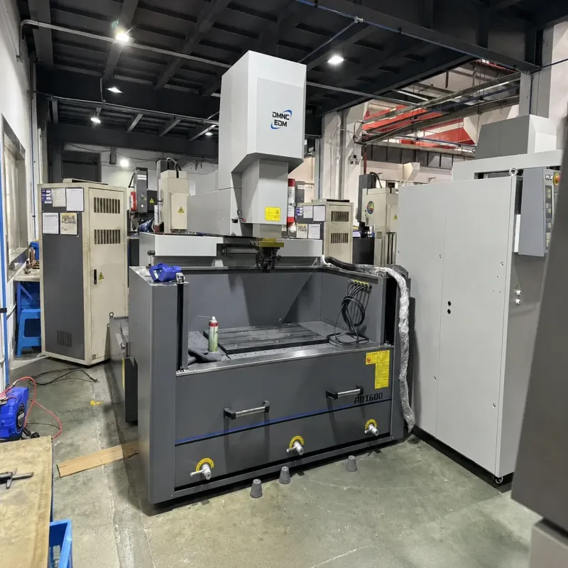
Set the engagement sequence deliberately. The heel should start contacting 0.02 mm before the core face reaches its shut-off position, so the lock is already built when the melt front arrives. Cut it the other way and the tip seals first, the melt pushes the core back, and the heel catches the core somewhere in the middle of the cavity pressure curve, too late to prevent the step.
Sizing follows the force. Compute projected tip area against peak cavity pressure, then give the heel a contact area that holds bearing stress under the steel's limit, with the taper angle steep enough to self-lock against slide recoil. Typical heel faces carry a 3 to 5 degree taper, matching the draft discipline used on vertical shut-offs.
Inspect the heel before the core tip during any flash investigation. A heel that has peened or lost its 0.02 mm early lock will show a witness step at the shut-off line, and no amount of clamp tonnage recovers it. The wider flash discipline, land-by-land, lives in the flash prevention guide; the heel is simply the feature most often forgotten in it.
Guide and Wear-Plate Design
The guide system decides whether the core arrives at shut-off on its planned line or a few micrometers off it. Branded or T-guide slides are the standard load carriers, running 0.01 to 0.02 mm clearance between guide and slide so the assembly slides freely but never rattles.
Never run a slide on soft shoe steel. Way covers and guide faces belong in hardened steel at HRC 54 to 58, ground rather than milled, because the pull direction load is steady and the wear is one-sided. Unhardened ways wear around 0.005 mm per 100,000 shots with thin lubrication, and the same pair at HRC 54 to 58 stretches that interval several times over.
Wear tells its own story through clearance. Total guide clearance of 0.03 mm is the replacement trigger for way covers. Below that number the part still tolerates the drift; above it the core tip arrives late and low, the shut-off prints a step, and the witness line moves around the part as cavity pressure changes day to day.
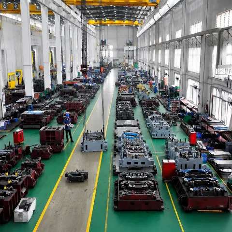
Lubrication is a design feature, not a maintenance habit. Put grease points every 200,000 to 500,000 cycles' worth of coverage along the guide length, metered so one pump feeds the face and not the cavity. Grease that migrates toward the core tip becomes a defect source: it outgasses at the melt front and stains cosmetic faces.
Two layout rules prevent the classic field failures. Keep the guide bearing length at least twice the core height above the parting line, so tip force never levers the slide onto its edge. And protect the guide faces during core-out at the end of travel: a hard stop in front of the pin entry, not behind the core, or the first bent cam pin is already scheduled.
Core Tip Cooling, Beryllium Copper and Polish
The tip of a side core is the worst-fed steel in the mold. A 4 to 6 mm section at the tip sits far from any drilled circuit, so heat leaves through a thread of metal instead of a channel. The tip runs 10 to 20 degrees hotter than the cavity face around it, the local part stays above the freeze temperature longer, and the cycle grows by 1 to 2 seconds on the copy that is supposed to be the fast one.
Two fixes carry the numbers. First, swap the last 15 to 25 mm of the tip to a beryllium copper insert. Be-Cu runs near 200 W/m·K against 25 to 45 W/m·K for tool steel, so the same tip that held a hot spot dumps heat several times faster through the copper path. The insert is pinned and seated in the core body so it can be replaced when the shut-off edge wears, rather than when the whole core is scrapped.

Second, cool the slide body itself. Where the core is larger than 10 mm at the base, drill 6 to 8 mm circuits into the slide block and land them within 15 to 20 mm of the tip steel. A bubbler or baffle in the blind end recovers most of the turbulence benefit of a through line.
Polish belongs to the pull direction. The pull face and any surface the part strips across should run Ra 0.2 to 0.4 micrometers, because static friction on a rough face drags the still-warm part sideways as the core exits, and the tear shows up as a white stress mark next to the undercut. The cavity-side sealing land gets the same treatment or finer: a 0.01 mm burr or polish scratch on a shut-off edge reads directly as a flash line on the part. Polish against the pull direction, never along it, so the part shears away cleanly instead of riding the peaks.
Failure Signatures With Numbers
Side cores fail legibly. Each signature maps to one root cause, and the micrometer reading tells you which one.
A witness step of 0.05 mm at the shut-off means the core arrived at a different place than the steel was cut to meet. Two causes cover almost every case: a guide worn past 0.03 mm total clearance, or a cracked or peened heel that let the core drift the 0.03 to 0.08 mm of push-back it was supposed to lock out. Check the heel first; it is cheaper to prove.
Scoring along the pull face points at lubrication or drag. Missing grease welds the slide onto its way cover within 10,000 to 50,000 shots and cuts visible grooves 0.02 to 0.1 mm deep. A single 0.01 mm burr on the core edge, left by a hard ejection collision, does the same thing one part at a time. Run a finger across the pull face under raking light before declaring a process problem.
A bent cam pin has one signature sequence. An angled pull that meets a locked or unsynced slide mid-cycle loads the pin at its 4:1 stick-out, and the pin yields before anything else in the stack gives. The lock usually traces back to a part that failed to strip, a slide parked by an earlier short shot, or an open stroke set shorter than the pull calculation. A low-pressure mold-saver profile on the first 100 cycles catches the collision at a fraction of the repair cost.
Recurring flash on one cavity out of many is usually assembly, not design. If three cavities run clean and one flashes, measure that slide's shut-off land against the drawing before blaming clamp force. A 0.02 mm shim error at the wear plate is enough at 40 to 60 MPa cavity pressure.
Short or stretched undercut dimensions on the part close the list. A core that does not seat fully against its heel leaves the undercut short by the missing travel; a slide that over-travels on open and slams its stop can chip the tip and pull steel the next shot does not replace. Both live in the CMM report, which is why the trial sequence should measure the undercut feature itself, not just the outline.
Breakaway and Telescoping Cores for Compound Undercuts
A compound undercut is one feature that needs two pull directions, typically a side hole with a second obstruction behind it. A single angled core cannot strip it, and a hydraulic unit on each axis multiplies cost fast. Two mechanical patterns handle most cases.
The breakaway core lets the part do the second movement. The core carries a stepped section separated by a designed weakness, and the stripper or the part itself snaps the step out of the second cavity as the piece leaves. The working number is a 0.1 mm radial gap at the break line, sized so the polymer shears at the undercut rather than tearing along a wall. Breakaway suits soft, unfilled grades and small undercuts; a glass-filled nylon above 25 percent fiber loads the break unpredictably and tends to stress-whiten the witness.
The telescoping core nests two pulls in one stroke. The outer sleeve is an angled core; the inner pin rides inside it and strips the deeper feature. Sequence is the whole design: the inner pin must release before the outer sleeve moves far enough to lose its own grip, and the entire core-out must finish before the ejector runs. A mistimed stack gives you a core moving into a part that is not yet free, which is the same collision that bends cam pins, just quieter.
For both patterns, keep the free length of the inner core under 3 times its diameter, and support the tip with a guide bushing in the outer sleeve. A 3 mm pin at 12 mm of unsupported stick-out deflects enough under melt pressure to put the undercut off-center by 0.05 mm or more. Where the compound feature becomes a thread, the clean answer is usually a motor-driven or rack-driven mechanical pull rather than a cam, and the torque math belongs to the unscrewing and rotary tooling family, not to the angled core.
When to Switch to a Hydraulic or Electric Core Pull
The angled pull has four hard boundaries. Cross any of them and the cylinder earns its price.
Pull length beyond roughly 100 mm pushes the stroke requirement out of the legal band. A 100 mm pull on a 20 degree cam needs about 280 mm of open stroke just for the core-out, and long shallow pins bend at the 4:1 stick-out limit no matter how carefully they are supported. A hydraulic pull takes the same 100 mm in its own cylinder and asks the mold only to open far enough to clear the part.
An undercut facing down defeats gravity's help and lets melt drain into the gap while the core sits exposed; a powered pull with a positive lock holds position regardless of orientation. Threads above a coarse pitch, parts that must not show any witness line from a cam-driven slide, and any pull that needs to sequence independently of mold motion all move to the same side of the line.
Cost is where the decision becomes arithmetic. One hydraulic or electric pull adds 1,500 to 4,000 dollars installed, plus the plumbing and the 3 to 7 day maintenance window per overhaul. The crossover on most jobs lands around three straight pulls per mold: below that, cam cores win decisively; above it, hydraulics start looking cheap because every cam is a stroke negotiation and every stack of cams is a serviceability problem. The full sizing and sequencing method for powered pulls is in the hydraulic core pull guide.
There is a middle option worth pricing before the hydraulic quote: a lift-plate or angled-pin core on a later plate. It buys a pull direction decoupled from the parting line at cam cost, and it is the right tool for two-cavity families that only need one deep side feature. The plate mechanics belong to the side-actions family: a cam on a lifter plate reads the same trigonometry, just on a second axis.
Maintenance Intervals and Wear Limits
Side cores are the highest-wear moving group in most injection molds, and they wear in a measurable line, not a cliff. Write the numbers into the tool file before the first production run, because a slide that reaches 0.03 mm of clearance mid-quarter will look like a process problem for two weeks before anyone measures it.
Unlubricated or thin-lubrication contact between a soft slide and a soft shoe loses roughly 0.005 mm of clearance per 100,000 shots. At HRC 54 to 58 way covers with metered grease, that rate drops several times over, which is the entire argument for hardened guides on a tool expected to run a million cycles. The replacement trigger is 0.03 mm of total clearance between guide and slide, measured with a feeler at both ends of the bearing length so taper is caught as well as gap.
| Item | Interval or limit | What is checked | Action at the limit |
|---|---|---|---|
| Guide clearance | Measure every 100,000 shots | Feeler at both ends of the bearing length | Replace way covers at 0.03 mm total clearance |
| Grease points | Every 200,000 to 500,000 cycles | Film present on the wear face, none at the tip | Clean and re-meter; check for cavity migration |
| Heel block face | Inspect at 250,000 shots | Blue-in contact pattern across the taper | Re-grind and restore the 0.02 mm early lock |
| Core tip shut-off land | Inspect at 250,000 shots | Edge condition under 3x magnification | Re-cut or swap the replaceable tip insert |
| Cam pin | Straightness check at 500,000 shots | Deflection against a surface plate | Replace above 0.05 mm over the pin length |
← swipe to scroll →
Table note: intervals assume two-shift production on engineering resins. Glass-filled grades at 30 percent loading wear guides 1.5 to 2 times faster and belong at half the inspection interval.
Keep a clearance log per slide, not per tool. On a 12 cavity mold with six slides, one runner that carries a heavier side load will open clearance twice as fast as its neighbors, and the flashing cavity tells you which one before the micrometer does. The trial record should carry the as-built clearance of every guide pair so the first service reads as a delta, not as a guess.

Side Core Design Checklist
Run this list on the drawing, before the first electrode is cut. Every line has a number attached, because a checklist of adjectives does not stop a 0.05 mm witness step.
- Stroke first. Confirm press open stroke from the datasheet, then set cam angle from pull divided by stroke. An 80 mm pull at 20 degrees needs 220 mm.
- Angle inside the band. Hold 15 to 25 degrees. Below 12 degrees the pin bends at 4:1 stick-out; above 30 degrees side load triples on the guide face.
- Heel sized to the pressure. Peak cavity pressure times projected tip area gives the push-back load. Set the heel to engage 0.02 mm before shut-off, taper 3 to 5 degrees.
- Guide specified. Branded or T-guide at 0.01 to 0.02 mm clearance, way covers hardened to HRC 54 to 58, bearing length twice the core height above the parting line.
- Lubrication metered. Grease points spaced for coverage every 200,000 to 500,000 cycles, routed away from the cavity.
- Tip heat handled. Any core tip under 6 mm at the section takes a beryllium copper insert or a local 6 to 8 mm circuit within 15 to 20 mm.
- Polish directed. Pull face at Ra 0.2 to 0.4 micrometers, sealing land finer, polished against the pull direction.
- Vent at the core shadow. Last-fill points behind a core need 0.01 to 0.02 mm vent depth with a 2 to 4 mm land, or the tip burns.
- Stop and sequence. Hard stop protects the guide faces, not the core tip. Core-out completes before the ejector runs, with 10 to 15 percent of pull reserved as late motion.
- Mold-saver profile. Low-pressure close verified on the first 100 cycles, with the cam pin collision as the case being tested.
- Serviceability. Tip inserts, way covers and heel faces listed as spares with part numbers, so a wear limit is a 30 minute swap and not a weld-rebuild week.
Side Core Design FAQ
Q1. What cam angle should a side core run?
Between 15 and 25 degrees, with 20 degrees as the default. At 20 degrees the tangent is 0.36, so each 100 mm of mold open stroke delivers 36 mm of pull. Shallow angles below 12 degrees demand stroke the press will not give and bend the pin at 4:1 stick-out; angles above 30 degrees multiply guide side load by 2 to 3 times.
Q2. When does a side core need a heel block?
Whenever cavity pressure acts on a core tip with more than about 1.5 mm of projected land. At 40 MPa an unheeled core is pushed back 0.03 to 0.08 mm per shot, which is enough to print a witness step or open a flash path. The heel engages 0.02 mm before shut-off so the lock is built before the melt front arrives.
Q3. What clearance should slide guides run?
0.01 to 0.02 mm between guide and slide on a branded or T-guide, with way covers at HRC 54 to 58. Replace the covers at 0.03 mm of total clearance. Unhardened pairs reach that limit in a few hundred thousand shots, at roughly 0.005 mm per 100,000.
Q4. Why is there a step on the part next to the side feature?
A witness step of 0.05 mm at the shut-off is a seat problem, not a clamp problem. Check the heel for a crack or peening first, then guide clearance. A core that arrives late, or arrives and then drifts 0.03 mm under pack pressure, leaves exactly that mark.
Q5. How long can an angled pull be before going hydraulic?
Roughly 100 mm. A 100 mm pull on a 20 degree cam needs about 280 mm of stroke, and shallow pins that long deflect. Below that length the cam wins on cost: a hydraulic cylinder adds 1,500 to 4,000 dollars plus plumbing and a 3 to 7 day maintenance window each time it is opened. The crossover for most molds sits around three straight pulls in one tool.
The Bottom Line
A side core is four numbers decided in order. The press datasheet gives the stroke. The tangent of the cam angle converts that stroke into pull distance. The projected tip area against peak cavity pressure sizes the heel, which must lock 0.02 mm before shut-off. The guide clearance of 0.01 to 0.02 mm on HRC 54 to 58 ways sets how long all three stay true, with replacement at 0.03 mm. Pick the angle before the pull, and the rest of the design follows the arithmetic.
DieStrike builds angled core, heel-locked and hybrid hydraulic tooling to IATF 16949 with ±0.005 mm mold accuracy, ±0.002 mm on EDM and jig-grinding, heat treatment to HRC 62, and a 120+ machine park behind the work. Injection molding programs are supported with supervised trial on 50 to 500 T presses, tool lead times of 2 to 5 weeks and standard components shipped in 3 to 7 days. Tier-1 accounts including TE, Amphenol, Luxshare and Dongshan run against our tolerance and documentation package. A mold design and DFM review checks the cam math, the heel lock and the guide life before any steel is cut, with feedback in 24 hours.
KEEP READING
Related Reading
How to Prevent Flash: Shut-Offs, Vents and Clamp Tonnage
The clearance and land numbers that stop melt escaping at every steel-to-steel joint.
Read articleArticleHow to Design an Unscrewing Mold: Motor, Rack and Stripper Action
When the undercut is a thread and a cam cannot strip it cleanly.
Read articleArticleHow to Mold Threads: Core Pulls, Unscrewing and Breakaway
Three thread forming routes with the torque, pitch and tolerance numbers behind each.
Read articleServiceMold Design and DFM
IATF 16949 mold design review with undercut strategy, cam sizing and heel lock checked before steel is cut. DFM feedback in 24 hours and tool lead times of 2 to 5 weeks.
Read articleNEXT STEP
Ready to Start Your Mold?
Send us your element dimensions or part numbers — our team responds within 24 hours with pricing and lead time.

Written by
Ray ChanMold Buyer's Guide Author · Precision Mold Manufacturing Specialist. Ray helps global importers, distributors and OEMs source factory-direct molds and mold parts.