
How to Design Die Casting Support Pillars: Spacing and Deflection
Table of Contents
A 900 mm by 600 mm die casting die with a 60 mm cavity plate ran 500 shots before a 0.08 mm fin opened along one edge of the shut-off. The clamp was sound, the platen was parallel, and the cavity block had been ground flat. The unsupported span between two support pillars measured 320 mm, which is 5.3 times the plate thickness, and 100 MPa of intensification pressure bent the steel past the flash threshold. Repair meant pulling the die, welding two dimples out of the bolster face, fitting a wider pillar set, and losing nine days of production on a 400-tonne cell.
This guide gives the deflection math, the pillar pitch rule, sizing and height tolerance, wear and thermal practice, and the load-path checklist that keeps cavity steel flat between 80 and 150 MPa.
The Snapshot
- Pillar pitch near 4 times plate thickness. A 60 mm plate carries a 215 mm unsupported span at 100 MPa inside a 0.02 mm deflection budget, and a 320 mm span has already opened a 0.03 mm flash path.
- Size at 12 to 40 mm diameter. Two to eight pillars per side carry the separating load, and the whole set must hold a 0.02 mm parallel height tolerance at the bolster face.
- Land 1 to 3 mm back from the cavity edge. Closer than 1 mm cuts into the cooling wall, and further than 3 mm leaves the cavity lip unsupported so it peens under load.
- H13 at 48 to 52 HRC with a 0.5 mm tip radius. Tip wear is measured every 20,000 shots, and a pillar set 0.5 mm short becomes a local load path that dimples the steel it was meant to protect.
What a Support Pillar Does in the Die Stack
A die casting die pushes molten metal into the cavity at 80 to 150 MPa of intensification pressure. That pressure acts on the projected area of the part and tries to push the two die halves apart. The machine clamp holds the halves together, but the steel between the cavity and the bolster is not rigid. A hardened support pillar is the post that carries the separating load from the back of the cavity block into the bolster or the clamp plate, so the cavity face stays flat and the shut-off stays closed.
A support pillar is not an ejector pin, a guide pillar or a leader pin. It does not move, it carries compression, and its only job is to stop a plate from bending between supports. Die casting practice uses 2 to 8 pillars per side at 12 to 40 mm diameter, with a 0.02 mm parallel height tolerance across the whole set. The tip seats on land 1 to 3 mm back from the cavity edge. Closer than 1 mm risks cutting into a cooling wall, and further than 3 mm leaves the cavity lip unsupported so it peens over after a few hundred thousand shots.

The load path runs from the gate outward. Molten aluminium at the gate applies pressure to the cavity block, the block presses on the support plate, the support plate presses on the pillar tips, and the pillars push that load into the bolster and the platen. Break the chain at any link and the plate bends. The same logic holds on the plastic side, where a large injection mold backs the core with support pillars for exactly the same reason, though at 40 to 80 MPa rather than 100 MPa.
On a 900 mm by 600 mm die, the support plate is often only 50 to 100 mm thick. Without a pillar array, a 300 mm or larger span across that plate bends under a full-pressure shot. The bend opens the parting line, and the parting line is where flash starts. A support pillar is the cheapest piece of steel in the stack and the one that decides whether the shut-off holds.
Deflection Math and the Pillar Pitch Rule
Plate deflection follows a fourth-power relationship, which is why span dominates every other variable. For a rectangular plate supported on four edges under uniform pressure, the maximum deflection is d = k x p x a^4 / (E x t^3). In that expression d is deflection in mm, k is a plate coefficient (0.00126 for clamped edges and 0.00406 for simply supported edges), p is cavity pressure in MPa, a is the unsupported span in mm, E is Young's modulus at 210,000 MPa for die steel, and t is plate thickness in mm.
Run it on a 60 mm support plate at 100 MPa. At a 120 mm span the deflection is 0.001 to 0.002 mm, which is tighter than the steel needs to be. At 240 mm it rises to 0.009 to 0.030 mm. At 360 mm the same plate reaches 0.047 to 0.150 mm, which is 1.5 to 5 times the flash threshold. The plate did not change and neither did the pressure; only the distance between supports changed.

The deflection budget is set by the flash threshold, not by a rule of thumb. Aluminium at 80 to 150 MPa enters a clean shut-off at a gap near 0.03 mm, so a support design should hold maximum deflection under 0.02 mm. Zinc is thinner at temperature and can flash through 0.01 to 0.02 mm, so a zinc die needs a tighter budget again. Set the budget first, then choose the span that meets it.
The common shop rule keeps pillar pitch at 4 to 6 times the plate thickness. The plate formula shows why the low end wins on a high-pressure die. At a 6 times pitch on a 60 mm plate the span is 360 mm, which deflects 0.047 mm clamped and 0.150 mm simply supported, both past the 0.03 mm flash threshold. Keep the working pitch near 3 to 4 times thickness on dies that run 80 to 150 MPa, and reserve wider spacing for low-pressure tools or thicker plates.
One more term decides whether the math applies at all: the pillar must actually touch both faces. A pillar set 0.5 mm short is not a support, it is a gap. The plate bends until it meets the tip, and that local contact punches a dimple into the back of the plate. Once the plate is dimpled, the pillar touches early, the surrounding area deflects further, and one short pillar makes the deflection worse rather than better.
Pillar Pitch Versus Plate Thickness
The table below converts the formula into working numbers for a support design that holds deflection at 0.02 mm across a flat shut-off. It assumes simply supported edges, which is the conservative case. A fully clamped edge or a die with a continuous backing plate allows a longer span, and a plate with a deep pocket or an open window allows less.
| Plate thickness (mm) | Cavity pressure (MPa) | Max span for 0.02 mm (mm) | Pitch as multiple of thickness | Typical pillar diameter (mm) |
|---|---|---|---|---|
| 50 | 80 | 200 | 4.0x | 12 to 20 |
| 60 | 100 | 215 | 3.6x | 16 to 25 |
| 60 | 150 | 195 | 3.3x | 20 to 30 |
| 80 | 100 | 270 | 3.4x | 25 to 35 |
| 80 | 150 | 245 | 3.1x | 30 to 40 |
| 100 | 150 | 290 | 2.9x | 35 to 40 |
← swipe to scroll →
Table note: spans are the maximum unsupported distance that holds plate deflection at 0.02 mm, using k = 0.00406 for simply supported edges and E = 210,000 MPa. Recalculate for the real edge condition, plate pocketing and thermal derating before a drawing is released.
Worked example on a 400-tonne cell. A part with a 200 mm by 200 mm projected area at 100 MPa generates a separating force of 4.0 MN, or about 408 tonnes, so the machine clamp sits close to its rating and the die has to be stiff. A 60 mm support plate with a 200 mm pillar pitch (3.3 times thickness) keeps center deflection at 0.004 to 0.014 mm. Eight pillars of 20 mm diameter, two per side, carry the load with a comfortable margin.
Worked example on an 800-tonne cell. A 280 mm by 280 mm projected area at 100 MPa generates 7.8 MN, or about 798 tonnes. An 80 mm support plate at a 250 mm pitch (3.1 times thickness) holds center deflection at 0.005 to 0.015 mm. Twelve to sixteen pillars of 30 mm diameter, three or four per side, spread the load so no single tip sees more than 650 kN.
The pillar diameter follows from the load per tip, not from habit. A 20 mm H13 pillar has a 314 mm² section, so a 650 kN tip load works out to about 2,070 MPa of contact stress across the full tip face. That is why a pillar works on a ground flat face and fails on a rounded or chipped one. Keep the tip flat, keep the face contact above 80 percent, and the compression stays inside the steel capability.
Flash Physics at the Shut-Off
A shut-off that opens by 0.03 mm is a flash channel, not a seal. On a die with a 300 mm perimeter, aluminium at 100 MPa enters that gap and leaves a 60 to 80 micron flash lip, and a full fin can run the whole perimeter inside 500 shots. The gap itself is almost invisible at the bench, because 0.03 mm is thinner than a sheet of copy paper, and the fin is the only visible evidence of the defect.
The flow through a gap rises steeply as the gap widens, so flash is a step function rather than a linear one. Each additional 0.01 mm of opening moves more metal per shot, and past the threshold the fin grows shot by shot instead of settling into a stable lip. That is why a deflection budget of 0.02 mm is not a safety margin, it is the working limit. Zinc is thinner at temperature and reaches its threshold at 0.01 to 0.02 mm, so the same die geometry needs a stiffer array in zinc than in aluminium.

A support pillar sits in that failure chain in two ways. A pillar set 0.5 mm short is a gap, so the plate deflects locally until it touches the tip, and that contact punches a 0.05 to 0.20 mm dimple into the back of the plate. Once the dimple exists, the pillar touches early at that point and the surrounding span grows longer, which opens flash around the dimple instead of closing it. A rounded or chipped tip causes the same local contact at the edge of the tip face.
The process side of the same defect is covered in the guide on preventing flash, where the causes run from clamp and tie-bar problems to metal temperature and vent depth. Establish the source before touching the machine. A fin that appears at one point while the clamp is sound, the platen is parallel and the tie bars are even is a deflection symptom, not a machine fault. Measure plate deflection with a dial indicator or a strain gauge on the support plate; if the measured deflection at the fin exceeds 0.02 mm, the fix is a pillar, not more clamp force.
Array Pattern and Load Path
The array goes corners first, mid-edges second, and the core of a long span last. A corner carries the highest load per unit area because two plate edges meet there, so the first four pillars protect the four corners of the support plate. Mid-edges come next because a plate deflects most at the center of each free edge. A central pillar or a row across the middle is only needed when the remaining unsupported span exceeds the 0.02 mm budget, which on a 60 mm plate means a span past roughly 215 mm.
Pillars must not sit where a cooling baffle, an ejector sleeve or a slide cam has to pass. On the drawing, the plate layout and the pillar array are fixed before the coolant is drilled and before ejector hole positions are wire-cut. A pillar is a solid 12 to 40 mm post with a flat tip, and it cannot share space with a 10 mm baffle hole or an ejector pin a few millimeters away. Keep at least 10 mm of clearance to any moving or drilled element, and more where a slide cam travels.
On a family die or a long-shot die, the runner block gets its own pillar under the sprue bush. The sprue bush takes the full injection force at a single point, and a long runner holds pressure longer, so that region needs a dedicated pillar rather than a share of the cavity array. A die casting gate and runner layout that spreads the fill also spreads the load, and the gate and runner design review should confirm where the pressure peak lands before the pillar array is fixed.
| Load-path check | Target | Method | Correction if failed |
|---|---|---|---|
| Pillar pitch against plate thickness | Pitch at 3 to 4 times thickness | Drawing review against the plate formula | Add a pillar or thicken the support plate |
| Parallel height across the set | 0.02 mm | Depth micrometer on a surface plate | Surface-grind the tip or shim 0.05 to 0.20 mm |
| Tip contact print | Above 80 percent of the tip face | Prussian blue on the bolster face | Reseat the pillar or replace the tip |
| Land setback from the cavity edge | 1 to 3 mm | CMM or gauge block on the block face | Re-cut the land position |
| Tip wear after service | Under 0.05 mm | Depth micrometer every 20,000 shots | Replace the pillar and log the height |
| Clearance to cooling and ejection | 10 mm minimum | Drawing clash check before drilling | Move the pillar to the next node |
| Hot-spot conduction | BeCu where the face passes 250 C | Thermal image at first trial | Fit a beryllium copper pillar |
← swipe to scroll →
Table note: check each row once at the drawing review and again at the trial run. A single failed row is enough to open flash under full intensification pressure.
Steel, Hardness and Tip Wear
H13 at 48 to 52 HRC is the baseline support pillar steel for a die casting die. Higher hardness resists peening but turns brittle under the point load at the tip, and lower hardness at 40 to 45 HRC is tougher but dents under the same load. Nitriding at 0.05 to 0.15 mm case depth and 900 to 1,100 HV puts a hard skin over a tough core, and hard chrome at 0.02 to 0.05 mm lowers friction and resists galling where the tip slides against the bolster face on assembly.
Finish the tip flat and blend a 0.5 mm radius at the edge. A sharp edge concentrates load and chips, and a heavily rounded tip reduces the contact area so the same load sits on fewer square millimeters. Do not shot-blast or descale the tip after grinding, because both round the face and change the contact print recorded at build. For lubrication, a graphite wash or a dry ceramic-based release is enough; grease carbonises near 250 C and packs into the shut-off where it becomes a witness mark.
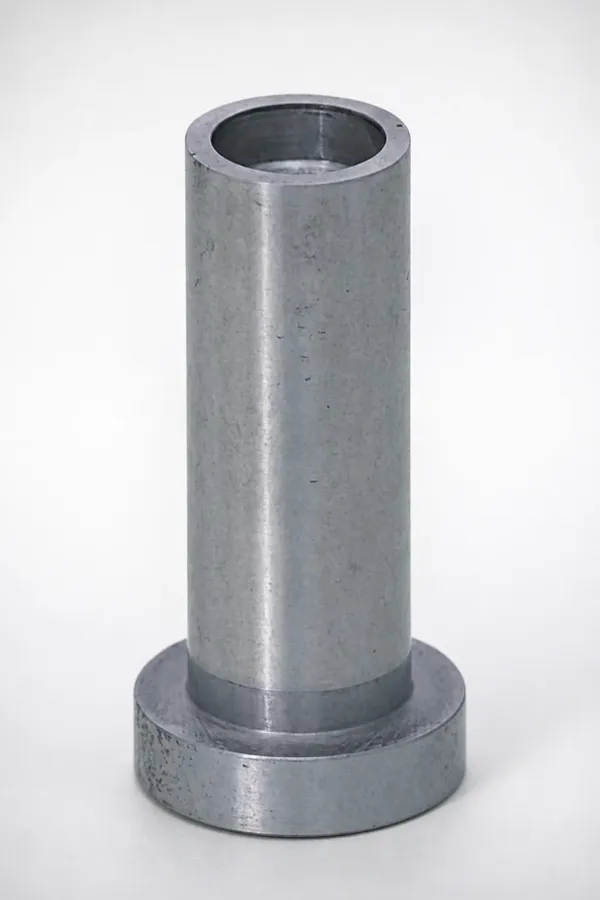
Measure tip height with a depth micrometer every 20,000 shots and write the number into the tool file beside the last set. Replace the pillar or re-shim when the total wear reaches 0.05 mm, because at that point the tip has lost about a quarter of its working tolerance against the 0.02 mm height band. Keep two spare pillars in the tool crib at each diameter in the die. A tip that wears to a visible flat at one corner shows up as a corner fin, and a standard component order runs 3 to 7 days, which is a full shift lost on a cell that must keep running.
The contact pattern is the early indicator. A new pillar prints evenly across the tip face, and a worn or cocked pillar prints on one edge first. Photograph the print at build, keep it in the tool file, and compare it at every service interval. The photograph costs nothing and it converts a fin that appears at shot 300,000 into a pillar change that happens at shot 250,000.
Thermal Pillars and Hot Spots
A pillar is a heat path as well as a load path. H13 conducts about 30 W/mK, so a steel pillar moves very little heat away from a hot spot. Where a local area runs at 250 C or above and heat checking starts on the cavity surface, a beryllium copper pillar (C17200 or C17510) drains heat into the bolster at roughly 200 W/mK, which is about six times the rate of the same shape in H13. That is the one case where a pillar is chosen for its thermal duty first.
Beryllium copper is softer, typically 30 to 40 HRC, and carries lower compressive strength, so it must be sized larger than the steel pillar it replaces. A 25 mm H13 pillar at 48 HRC becomes a 35 to 40 mm BeCu pillar for the same load. Use it as a combined support and conduction pillar at an isolated hot spot, not as the main load path for the whole die, and finish the tip to the same 0.02 mm height band as the rest of the set.
The height tolerance is really a hot-tolerance, not a cold one. A 60 mm H13 pillar grows about 0.13 mm from 25 C to 200 C at a coefficient near 12 x 10^-6 /C, and the plate it bears on grows as well, so a set that is flat cold can sit 0.02 to 0.05 mm proud or short once the die is at temperature. Fit and check the parallel in a warm die, or keep a cold shim allowance of 0.02 to 0.05 mm and verify it at the first trial. The die casting die cooling design sets the temperature field the pillars see, so the two layouts belong on the same drawing review.
Thermal images taken at the first trial are the cheapest proof of where a pillar should sit. A face that runs 30 to 50 C hotter than its neighbors over a 100 mm patch is a candidate for a BeCu pillar, or for a cooling change if one is available. Add the pillar only after the cooling circuit has been reviewed, because a BeCu pillar that drains heat into a bolster plate without a cooling path simply moves the hot spot rather than removing it.
Fitting, Inspection and Retrofit
Check the fit with Prussian blue on the bolster face before every trial run. The contact print at each tip should cover at least 80 percent of the tip face. A tip that prints on one edge is cocked, and it will peen that edge and open a gap on the opposite side, which reads later as a corner fin with no obvious cause.
Set the parallel height with a depth micrometer on a surface plate, comparing every tip against the tallest one in the set. Hold the 0.02 mm band across the whole array, not just per pillar. Grind for the first fit and use ground spacers of 0.05 to 0.20 mm only as a field correction, because a stack of shims compresses under load and changes the contact pattern that was verified at build.
Retrofit a pillar when the die shows a fin at a single point while the clamp is sound and the rest of the shut-off is clean. Add the pillar, or shim an existing one by 0.05 to 0.20 mm, before reaching for the welder. Welding up a dimple in the bolster face and re-machining it is the last step in the sequence, because the weld leaves a heat-affected zone that needs stress relief and re-grinding before it can carry load again. A die casting tool shop that builds and services die casting molds treats the pillar array as a serviceable feature, not a one-time build detail.
Record three numbers for every pillar at every service interval: tip height, contact print percentage and shot count at inspection. The 20,000 shot interval is short enough to catch wear before it opens a gap and long enough to fold into a normal maintenance stop. Any fin that appears between two inspection intervals is evidence that the interval is too long for that die, so shorten it rather than guessing at the next repair.
Cost, Build Time and Design Discipline
A support pillar is a small cost against the alternative. A nitrided H13 pillar at 20 to 40 mm diameter is a standard component with a 3 to 7 day lead time, and a complete die casting mold runs 2 to 5 weeks from drawing release. A retrofit set of eight pillars with ground spacers is a few hundred dollars in parts plus one shift of fitting, against a nine-day production stop and a bolster repair that needs the die stripped, welded, stress-relieved and re-ground.
The design sequence matters more than the part cost. Freeze the pillar array on the die drawing before the coolant drill touches the plate, before ejector hole positions are wire-cut and before the slide cam pocket is milled. A pillar added late has to dodge every hole already in the support plate, so the order is plate layout, then the pillar array, then cooling, then ejection. Reversing that order is the most common reason a die ends up with an uneven pillar spacing and a soft spot in the middle of the span.
Compare a pillar against extra plate thickness before adding either. Moving a support plate from 60 mm to 80 mm raises the plate cost by roughly 30 to 40 percent and adds 20 mm to the die stack height, which can push the die past the machine daylight or force a change in the ejector stroke. Pillars add stiffness exactly where the span is long, at a fraction of the material cost, and they are replaceable when they wear instead of forcing a plate re-cut.
The array is also a service feature. A pillar can be ground, shimmed or replaced in a maintenance window, while a deflected support plate has to be pulled, machined flat and re-fitted. Designing for the service action means leaving access to every pillar tip from the bolster side and keeping the tip height record in the tool file from the first trial.
Die Casting Support Pillar FAQ
Q1. How many support pillars does a die casting die need?
Enough to hold the unsupported span at or below the pitch that meets a 0.02 mm deflection budget. On a 60 mm support plate at 100 MPa that span is about 215 mm, so a 400 mm wide part usually needs three or four pillars per side. Corners first, then mid-edges, then a center pillar if a span still exceeds the budget.
Q2. What tolerance applies to support pillar height?
A 0.02 mm parallel height tolerance across the whole set at the bolster face. A pillar outside that band either fails to carry load or carries it early, and early contact punches a dimple into the plate. Check the band in a warm die, because a 60 mm H13 pillar grows about 0.13 mm from 25 C to 200 C.
Q3. Why did a fin open when the clamp is sound?
Because a fin at a single point with a clean clamp, parallel platen and even tie bars is a deflection symptom. Measure the support plate deflection; if it exceeds 0.02 mm at the fin, add a pillar or shim an existing one by 0.05 to 0.20 mm. More clamp force does not close a gap that the plate geometry opened.
Q4. Where should a pillar sit relative to the cavity edge?
On land 1 to 3 mm back from the cavity edge. Closer than 1 mm risks cutting into a cooling wall or a baffle hole, and further than 3 mm leaves the cavity lip unsupported so it peens over after a few hundred thousand shots. Keep 10 mm minimum clearance to any ejector or slide element.
Q5. When should a pillar be beryllium copper?
When a local area runs at 250 C or above and heat checking starts. Beryllium copper conducts about 200 W/mK against 30 W/mK for H13, so it drains the spot into the bolster. Size it larger than the steel pillar it replaces, because BeCu at 30 to 40 HRC carries less load per square millimeter.
The Bottom Line
A die casting die stays flat when the support array keeps the unsupported span inside a 0.02 mm deflection budget at full intensification pressure. On a 60 mm plate at 100 MPa that means a pitch near 215 mm, 12 to 40 mm pillars on land 1 to 3 mm back from the cavity edge, and a 0.02 mm parallel height tolerance across the set. Aluminium enters a 0.03 mm shut-off gap, so deflection, not clamp force, decides whether a fin opens.
Hold the load path from the gate to the bolster without a gap, check the contact print on every tip before each trial, and measure tip wear every 20,000 shots. A worn or short pillar costs a few hundred dollars to replace and a production stop to ignore. DieStrike builds die casting and precision molds to IATF 16949 with 0.005 mm mold accuracy and 0.002 mm on EDM and jig-grinding, HRC 62 maximum cavity hardness, 120+ machines and standard components in 3 to 7 days. Die casting mold lead times run 2 to 5 weeks, with DFM feedback inside 24 hours.
KEEP READING
Related Reading
How to Design Die Casting Gates and Runners
Gate area, runner taper and overflow placement for the fill pattern that keeps pressure even across the cavity.
Read articleArticleHow to Select and Maintain a Shot Sleeve
Sleeve bore, clearance and wear limits against plunger tip life on a hot chamber or cold chamber cell.
Read articleArticleHow to Design Vacuum-Assisted Die Casting Dies
Vent area, vacuum block and seal routing for dies that evacuate the cavity before the shot.
Read articleServiceDie Casting Mold Manufacturing
IATF 16949 die casting tooling with 0.005 mm mold accuracy, 120+ machines and 2 to 5 week lead times.
Read articleNEXT STEP
Ready to Start Your Mold?
Send us your element dimensions or part numbers — our team responds within 24 hours with pricing and lead time.

Written by
Ray ChanMold Buyer's Guide Author · Precision Mold Manufacturing Specialist. Ray helps global importers, distributors and OEMs source factory-direct molds and mold parts.