
How to Improve Cooling on an Existing Mold: Retrofit Options
Table of Contents
A 24 cavity closure mold came out of a two week shutdown running 38 second cycles where the tool had held 26 seconds. Half the circuits carried 0.4 mm of calcium scale, the far cavities ran 11 degrees hotter, and the plant already had a quote for a replacement mold at 96,000 dollars. A 3,200 dollar descale plus a manifold change cut the cycle to 27 seconds inside one week. That gap between scrapping and retrofitting is usually four measurements.
This guide covers the retrofit menu on an existing tool, from a low-risk descale to a printed conformal core, with a cost band and cycle gain on each option. Channel cleaning procedure belongs to cooling channel maintenance, and structural weld repair of the same blocks belongs to mold repair and maintenance.
The Snapshot
- Scale costs 10 to 15 percent of cycle. A 0.3 to 0.5 mm deposit in a 10 mm channel insulates the steel wall, and heat transfer drops 20 to 40 percent before the flow rate moves at all.
- Series circuits run the last cavity 8 to 12 degrees hotter. Coolant picks up 2 to 3 degrees per cavity in one loop, so a six cavity series path feeds its final cavity with the warmest water in the tool.
- A 6 to 8 mm channel cannot carry the flow. Turbulent flow needs 4 to 8 L/min per circuit, and a 6 mm bore needs 2.5 times the pressure of an 11 mm bore for the same velocity.
- Circuits and inserts pay back in 3 to 9 months. On a 30 second cycle at 6,000 machine hours a year, one second saved frees 200 hours of press time.
Baseline First: Flow, Delta T and Cycle Split
Every retrofit starts with four readings taken on the running tool in a single shift, at production temperature. Flow comes first, read with a clamp-on ultrasonic or turbine meter on each circuit at the header pressure the plant actually runs. A circuit returning 2.1 L/min where its neighbours return 6.8 L/min is scaled, air-locked or plumbed in series with three other cavities.

Delta T comes second, measured on the inlet and outlet of one circuit 30 minutes into a steady run: 3 to 5 degrees is normal, and 8 degrees or more means too little water for the heat being picked up. The cavity face is third, surveyed with a thermal camera within 5 seconds of opening at six points or more, with a 5 degree target between cavities.
The cycle split closes the baseline. Time injection, pack and hold, plastication, cooling and ejection separately, because cooling covers 50 to 70 percent of the cycle in a well-cooled tool. If plastication or pack owns the time, no cooling retrofit shortens the cycle and the money belongs elsewhere.
| Reading | How to take it | Comfortable value | What it points to |
|---|---|---|---|
| Flow per circuit | Clamp-on ultrasonic meter on each circuit at running temperature | 4 to 8 L/min at 1 to 2 bar | Descale, re-drill or split the loop |
| Coolant delta T | Contact probes on the inlet and outlet of one circuit | 3 to 5 degrees | Raise flow or shorten the circuit |
| Cavity face spread | Thermal camera within 5 seconds of opening, six points | Within 5 degrees cavity to cavity | Inserts, baffles or conformal pockets |
| Part weight spread | 30 consecutive shots on a 0.001 g balance | Under 0.5 percent | Circuit balance and flow verification |
← swipe to scroll →
Table note: readings are typical values for a 4 to 24 cavity tool on water at 20 to 60 degrees Celsius. Confirm against the tool drawing, the chiller capacity and the recorded trial sheet before committing to a retrofit scope.
The Four Bottlenecks That Make a Mold Run Hot
Four patterns account for almost every hot mold that reaches a shop for rework, and each one has a different repair.
The first is scale. Deposits of 0.3 to 0.5 mm build up over 6 to 24 months in hard water, and their thermal conductivity sits near 1 to 3 W/m·K against 25 to 45 W/m·K for tool steel. That layer blankets the wall between the water and the steel, and flow rate falls last, which is why the problem is easy to miss.
The second is the series circuit. When four or six cavities share one path, the coolant enters cold and leaves warm by 8 to 12 degrees, and the last cavity sees the hottest water. On a 16 cavity tool this alone can put a 6 to 15 degree steel spread across the cavity set, and the hot cavity sets the cycle for the whole tool.
The third is channel size. A high-cavity tool built with 6 to 8 mm channels can pass the required flow only at high pressure, and many plants run it laminar instead. At an 8 mm bore the pressure needed for turbulent flow is roughly 2.5 times that of an 11 mm bore at the same velocity, so the mold looks plumbed correctly and still moves about half the heat per degree of rise.
The fourth is geometry: tall cores and deep bosses with no path through them. A core standing 60 mm tall with a 12 mm bore has no room for a straight channel, so the steel at the tip runs 20 to 40 degrees above setpoint. Because cooling time scales with the square of wall thickness, an effective 4 mm wall where 1 mm was designed costs 16 times the cooling time in that zone.
Descaling and Mechanical Cleaning
Descaling is the cheapest retrofit on the list and the best ratio of gain to risk. A tool that has run two years on untreated water and returns 10 to 15 percent cycle after cleaning is normal, and the cavity block is not machined at all.
Chemical descaling circulates an inhibited acid at 40 to 60 degrees for 30 to 120 minutes, then neutralises and adds a rust inhibitor. The inhibitor matters: an un-inhibited acid attacks brazed joints, aluminium plates and some seal materials in under an hour. Mechanical cleaning covers a 3 mm rotary tube brush, high pressure water at 150 to 300 bar, and dry ice blasting at minus 78 degrees.

Two things go wrong. A circuit that opens up can reveal a leak at a weld or fitting that scale had been sealing, and over-flushing drives debris into a bend where it settles. Verify with a borescope on the long circuits and compare every flow figure with the baseline.
Resizing Channels and Splitting Series Circuits
A channel that is too small can sometimes be drilled larger. The limit is the web of steel left between the channel wall and the cavity face: keep 2.5 to 3 mm minimum, and space parallel runs 3 to 4 times the channel diameter apart. Check it with an ultrasonic thickness gauge on every run before the drill goes in, because a 12 mm channel under a cavity face needs 15 to 18 mm from the face to the channel axis.
Re-drilling an 8 mm path to 11 mm raises the flow at the same pressure by roughly 3.5 times and often returns 15 to 25 percent of the cycle. The work happens on the bench with the block out of the press, at 1,500 to 6,000 dollars for a high-cavity tool. Nothing can be added back, so a block that fails the web check moves to the next option.
Where the channels are the right size but the loop is wrong, split the series path into four to six parallel branches on a manifold, each with a flow meter or needle valve. Keep branch lengths within 15 to 20 percent of each other and the header under 1 m/s, and check the chiller first: eight branches at 4 to 8 L/min need 32 to 64 L/min of flow and 2 to 3 bar of pump head. A six cavity loop that ran its last cavity 10 degrees hot typically comes back within 3 degrees, and the water side of the work is usually a job for the mold heating and cooling range.
Baffles, Bubblers and Heat Pipes in Tall Cores
Tall cores, thin blades and deep bosses are the zones a straight drilled channel cannot reach. Three devices solve that geometry, and all three fit a hole that already exists or can be drilled from the back of the insert. Plate, tube and phase-change options are compared in more detail in baffles and bubblers for mold cooling.

A baffle is a plate pressed into a drilled hole leaving 0.5 to 1 mm of clearance each side, so water travels up one side and down the other instead of short-circuiting across the top. Baffles suit cores with a 12 to 25 mm bore, cost 150 to 400 dollars per position, and typically recover 20 to 30 percent of the cooling time in that zone.
A bubbler feeds water up a tube and returns it down the annulus, with the tube end within one or two diameters of the core tip, and is the standard answer for cores of 8 to 20 mm: a 6 to 10 mm hole through the core, and 20 to 35 percent off the cooling time of that feature. A heat pipe covers the blade under 6 mm thick where no hole fits, behaving like a conductor of 5,000 to 20,000 W/m·K at 250 to 900 dollars per position.
Two risks repeat across all three. Brazing next to a core can move it 0.02 to 0.05 mm, so straightness and the shut-off are checked afterwards. A baffle plate that is not staked or pinned can work loose after 200,000 to 500,000 cycles and block the flow it was installed to improve.
Copper, Beryllium and Spray Inserts for Hot Spots
Local hot spots respond best to local conduction. Copper alloys such as beryllium copper and CuCrZr conduct at 300 to 400 W/m·K, which is 5 to 8 times the 25 to 45 W/m·K of tool steel, so an insert at a thick section pulls heat out of the steel and hands it to a nearby circuit.
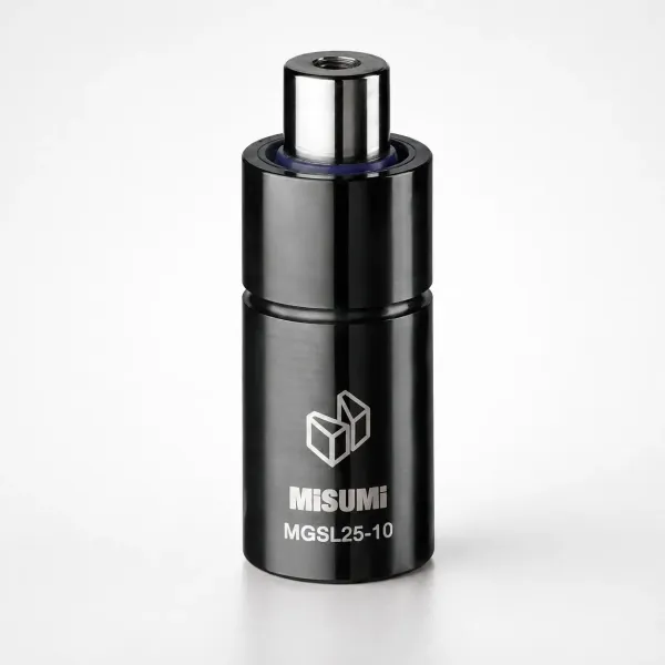
The insert is machined into a pocket with a 0.01 to 0.02 mm fit, pressed or bolted in with a cooling channel drilled through it, and assembled with thermal paste rated at 1 to 3 W/m·K. Cost lands between 400 and 1,500 dollars per position with 2 to 5 days of machining, and a well-placed insert removes 15 to 30 degrees from the hot spot and takes 10 to 20 percent off the cycle.
One rule governs placement. Never put copper on a shut-off face, a seal land or an ejector bore carrying a sliding load, because beryllium copper sits near HRC 30 to 40 and will peen under repeated closing. Two cheaper variants cover tight geometry: a spray insert feeds a tube with 0.5 to 1 mm holes that spray the back of a cavity wall, and a slotted insert is milled with 0.5 to 1 mm slots around a core pin outside the cooling bore. Both cost 200 to 800 dollars and work best on a parallel circuit.
Printed Conformal Inserts and Slide Spot Cooling
Where the geometry blocks every conventional path, a printed insert puts a channel wherever it is needed. The pocket is machined 0.2 mm oversize, the printed piece is bonded or bolted in with 0.05 mm clearance and a face 0.5 to 1 mm under the cavity surface, and the internal channels follow the part contour at 3 to 5 mm diameter with 8 to 15 mm spacing. Design rules belong to conformal cooling design.
Printed inserts run 3,000 to 12,000 dollars per position with a 2 to 4 week lead time, so they lose to baffles on a simple core and win on a deep draw or a long rail, at 25 to 50 percent gain on the local zone and 10 to 20 percent on the whole cycle. Slides are the quieter problem: a slide travelling 100 to 200 mm receives almost no cooling and runs 40 to 60 degrees above the block, which shows up as warp or a short-shot corner. A 6 mm channel in the slide body, or a cooling plate bolted under the slide face with 0.05 mm clearance, costs 600 to 2,500 dollars and recovers 1 to 3 seconds.
Welding, Re-Polishing and Leak Integrity
Most retrofits end with a weld: a channel plugged after re-drilling, a boss built up, a cracked water line closed. Heat input decides whether that weld survives. In H13 or 1.2343, preheat to 250 to 350 degrees, weld with matching filler under TIG at 150 to 250 A, and cool under a heat blanket at no more than 50 degrees per hour.
A cold weld in H13 leaves a heat affected zone 0.3 to 1.5 mm wide that can harden to HRC 55 beside softer base metal, and that mismatch cracks 2,000 to 5,000 shots after the repair. A block that sees more than 300 degrees takes a post-weld temper of 2 hours at 500 to 550 degrees. Dye penetrant inspection per ASTM E165 follows the grind, then every circuit carries a hydro test at 1.5 times working pressure: 12 bar for 10 minutes on a tool that runs at 4 to 8 bar, then a 24 hour hold to look for weeping.
Re-polish only what will be visible, and re-measure what supports a tolerance. Welding beside a shut-off can move the steel 0.02 to 0.05 mm, so the shut-off is checked by die spotting or CMM before the tool runs. Visible surfaces finish at SPI A-1 to A-3, and shut-off faces hold plus or minus 0.005 mm, or plus or minus 0.002 mm where an insert was jig-ground.
When a New Core Block Beats Rework
Every retrofit list needs a stop rule, because reworking a tired block can cost more than replacing it. Four conditions favour a new core insert: more than about 30 percent of the cooling layout has to change, less than 2.5 mm of web on the ultrasonic check, seal lands opened past 0.01 mm with guide pin bores at 0.03 mm of play, or heat checking across the cavity face.
The fifth condition is life. A tool with fewer than 12 months of production left rarely earns a 20,000 dollar insert, and a descale is the correct spend. A new core insert runs 8,000 to 25,000 dollars with a 2 to 5 week lead time, weighed against downtime of 2,000 to 15,000 dollars a day on a mid-tonnage press.
Verification: Cycle Study, Cavity Delta and Leak Test
A retrofit is not finished when the tool goes back in the press. It is finished when the same four readings that opened the project are taken again, from a 100 shot study at production setpoints rather than a warm-up run.

The cycle split comes first, with the same shot weight and setpoints on both runs. Then the cavity delta from a thermal camera survey at six points, where 5 degrees or less between hottest and coldest cavity is the target. Part weight spread is the cheapest process proof: 30 consecutive shots on a 0.001 g balance, a spread under 0.5 percent, and flow per circuit within 10 percent of target.

Leak integrity closes the job: hold at working pressure for 24 hours with dry fittings and inspect every plug, weld and hose barb. Release the tool only after a full production shift, with 30 shots of capability data, a scrap count and a note of any cavity still more than 5 degrees off its neighbours. Then update the tool file with the new drawing revision and flow figures.
Payback Math Against the Machine Hourly Rate
The arithmetic is short. Machine hours saved equal annual machine hours multiplied by one minus the ratio of new cycle to old cycle, so a tool running 6,000 hours a year that drops from 30 seconds to 27 seconds frees 600 hours of press time. At 60 dollars an hour that cycle gain is worth 36,000 dollars a year and repays a 12,000 dollar insert in about four months. At a 45 dollar rate the payback stretches past five months, and at 120 dollars for a large press the same change repays a 25,000 dollar block inside a quarter.
| Retrofit option | Typical cost | Cycle gain | Check before committing |
|---|---|---|---|
| Descaling, chemical or mechanical | 400 to 3,200 dollars | 10 to 15 percent | Aluminium plates, brazed joints, seal materials |
| Channel re-drilling to 10 or 12 mm | 1,500 to 6,000 dollars | 15 to 25 percent | 2.5 to 3 mm minimum web above the channel |
| Splitting a series loop into branches | 800 to 3,500 dollars | 15 to 25 percent | Chiller flow and available pump head |
| Baffles and bubblers in tall cores | 150 to 900 dollars per position | 20 to 35 percent in that zone | Drilled hole size, brazing distortion |
| Copper insert for a hot spot | 400 to 1,500 dollars per position | 10 to 20 percent | Keep it off shut-offs and seal lands |
| Printed conformal insert in a pocket | 3,000 to 12,000 dollars | 25 to 50 percent in that zone | Pocket depth and a 2 to 4 week lead time |
| Slide and lifter spot cooling | 600 to 2,500 dollars | 1 to 3 seconds | Hose routing and slide clearance |
| New core insert instead of rework | 8,000 to 25,000 dollars | 20 to 40 percent | Remaining tool life and a 2 to 5 week lead time |
← swipe to scroll →
Table note: cost bands are typical 2026 shop values for rework on an existing tool in North America and Europe, excluding freight and downtime. Cycle gains assume the cooling loop is the limiting factor, so confirm each one against a full-plant quote.
Two secondary savings belong in the same sum. A cavity spread that drops from 12 degrees to under 5 usually takes the reject rate from 2 to 6 percent down toward 1 percent, and pump and chiller power of 10 to 25 kW falls per part as the cycle shortens.
Mold Cooling Retrofit FAQ
Q1. Where should I start on a mold that runs hot?
With four readings on the running tool: flow per circuit, inlet to outlet delta T, a thermal camera survey at six or more cavity points, and the cycle split. They separate a plumbing problem from a cavity problem at the cost of one shift.
Q2. How much cycle can a descale recover?
10 to 15 percent is typical on a tool that has run two years on untreated water with 0.3 to 0.5 mm of deposit. Confirm with a flow reading before and after, because a circuit that gains no flow was not scaled.
Q3. Can an existing block be drilled to larger channels?
Only if 2.5 to 3 mm of steel remains between the channel wall and the cavity face, verified with an ultrasonic thickness gauge. Going from 8 mm to 11 mm raises flow at the same pressure by roughly 3.5 times and often returns 15 to 25 percent of the cycle.
Q4. When is a new core insert cheaper than more retrofit work?
When more than 30 percent of the cooling layout has to change, when the web is under 2.5 mm, or when seal lands have opened past 0.01 mm. A new insert costs 8,000 to 25,000 dollars with a 2 to 5 week lead time.
Q5. How do I prove the retrofit worked?
Repeat the four baseline readings on a 100 shot study, add a 30 shot part weight check for under 0.5 percent spread and a 24 hour pressure hold for leaks, and confirm the cavity face sits within 5 degrees before release.
The Bottom Line
Most hot molds do not need a new tool. They need a flow reading, a delta T reading, a thermal survey and a cycle split before anyone spends money. Those four numbers point to scale, to a series circuit, to a channel that is too small or to a core with no water path at all.
The retrofit menu runs from a 400 dollar descale to a 12,000 dollar printed conformal insert, and each option carries a known cycle gain, a known risk and a payback that can be checked against the machine hourly rate. The tools that get scrapped early are usually the ones that were never measured.
DieStrike builds and reworks injection molds and stamping dies under IATF 16949 process control, with plus or minus 0.005 mm mold tolerance, plus or minus 0.002 mm on EDM and jig-ground features, heat treatment to HRC 62 maximum, 120 or more machines and tier-1 programs for TE, Amphenol, Luxshare and Dongshan. Standard components ship in 3 to 7 days and tool lead times run 2 to 5 weeks. Send the tool drawing, the current cycle sheet and the four baseline readings, and we will return a retrofit scope with a cost band and cycle gain for each option.
KEEP READING
Related Reading
How to Design Conformal Cooling Channels
Channel diameter, spacing and build routes for printed cores, with the flow numbers that make them pay.
Read articleArticle5 Mold Cooling Channel Design Tips
Diameter, spacing, circuit length and baffle rules that keep a cavity face even within a few degrees.
Read articleArticleHow to Choose a Mold Temperature Controller
Pump capacity, kW, flow rate and the setpoint accuracy a tight-tolerance tool needs.
Read articleServiceMold Repair and Maintenance
Retrofit cooling, split circuits and rework hot spots on existing tools under IATF 16949 process control.
Read articleNEXT STEP
Ready to Start Your Mold?
Send us your element dimensions or part numbers — our team responds within 24 hours with pricing and lead time.

Written by
Ray ChanMold Buyer's Guide Author · Precision Mold Manufacturing Specialist. Ray helps global importers, distributors and OEMs source factory-direct molds and mold parts.