
How to Plan a Piloted Hole Pattern in a Mold: Pilots, Dowels
Table of Contents
A four-plate mold reached assembly with dowel holes that would not take a pin. Every hole measured fine on the CMM against its own plate. What nobody checked was where the pattern sat once each plate was drilled from its own program origin: a 12 mm twist drill had wandered 0.12 mm off position at 35 mm depth in pre-hard P20, and the joint lost 0.24 mm. The shop spent two days hand-fitting boron dowels while the trial slot burned.
This guide covers the piloting sequence, the reamed class you ask for, the stack math behind a dowel joint, and the RFQ wording that gets the pattern cut right the first time.
The Snapshot
- Pilot first. A guide pin or pilot bushing forces the twist drill to enter concentric with its finished axis, which stops wander at its source.
- Interference is small on purpose. Dowel holes ream to plus 0.01 to 0.03 mm, and A-3 pins press in at 0.01 to 0.03 mm interference. A pin that falls freely by hand is the acceptance test.
- The stack budget is tight. A true-position callout of 0.02 mm on two plates allows up to 0.04 mm of shift at the joint. If the dowel already carries 0.02 mm, nothing is left for shims.
- Depth rules out the drill. A blind hole deeper than 4 times its diameter wants peck cycles at 1 to 3 times diameter with through-tool coolant, or the flutes pack and the drill snaps.
Why a Twist Drill Wanders
A twist drill cuts on its two outer corners and does almost nothing at its center. The web between the flutes leaves the chisel edge with a negative rake near zero degrees, so that edge squeezes material instead of shearing it. The squeezing needs rotation to clear, and rotation around a wobbly axis is exactly what wander is.
The second mechanism is geometry at entry. Any asymmetry in hardness, any patch of scale, any sloped surface the tip touches first pushes the drill off center within the first millimeter of cut. From that moment the hole follows the entry, not the drawing.

Wander grows with slenderness because a drill behaves like a column under lateral load. The deeper the hole, the smaller the side force needed to bend the flutes. The length-to-diameter ratio, not the machine, decides the error band you can defend.
Practice shows the size of the problem. A 10 mm twist drill in pre-hard P20 at 280 to 330 HB typically lands 0.10 to 0.30 mm off position after 30 mm of depth. The same drill in hardened tool steel drifts less because the material holds the web rigid, but the cut only works with carbide, oil coolant and feeds small enough to make production drilling a bad bargain.
Position accuracy in a mold plate therefore comes from controlling the drill at entry, then reserving final size for a tool that cannot wander. A reamer has no chisel edge and pilots in its own finished bore. A drill has both failure modes at once. That difference is the whole argument for a piloting program.
The Six-Step Piloting Sequence
The sequence below is the shop method for a dowel or fastener hole that must hold position across a two-plate joint. It works because every step inherits the axis of the step before it, and because the mating plate itself supplies that axis.
Step one: spot the hole with a solid or carbide center drill to a 60 degree point. The recess only needs to seat the drill tip, roughly half the drill diameter deep. A shallow pilot also keeps the twist drill from free-falling into a deep starter hole and taking up its own angle.
Step two: drive the entry from a hardened guide. Either press a pilot bushing into the machine table or a fixture plate, or press a guide pin into the mating plate and drill through it. The bushing or pin forces the twist drill to enter concentric with the finished axis. This step is the entire reason mold shops can repeat a pattern across two plates without a coordinate boring machine.
Step three: drill to 90 to 95 percent of final diameter. The pilot keeps the entry straight, the smaller core leaves an even wall for the reamer to take, and the hole stays round enough to guide the next tool.
Step four: taper-ream by hand or on the machine to open the bore close to size, letting the long taper find the axis rather than force it. Step five: machine-ream to the stated class with a spiral-flute reamer, 4 to 8 mm of full-diameter lead, cutting fluid matched to the steel. Step six: deburr the entry and exit faces, then measure with a pin gauge the assembly will actually see.
| Step | Tool | Size or allowance | Acceptance check |
|---|---|---|---|
| 1. Spot | Center drill, 60 degree point | Depth about half the drill diameter | Recess concentric, no broken edge |
| 2. Pilot | Hardened guide pin in the mating plate, or a pilot bushing in the fixture | Pin at the finished hole class | Drill enters without deflecting at the surface |
| 3. Drill | Twist drill through the pilot | 90 to 95 percent of final diameter | Hole open and round at both faces |
| 4. Taper ream | Taper ream, hand or machine | 0.1 to 0.2 mm under final | Even, bright cut on all flutes |
| 5. Machine ream | Spiral-flute reamer to class | Final class, for example plus 0.01 to 0.03 mm | Pin gauge enters by hand weight |
| 6. Deburr and check | Countersink stone, pin gauge, square | Break 0.2 to 0.5 mm at each face | Square within 0.01 mm over depth |
← swipe to scroll →
Table note: allowances are typical shop values for reamed holes in pre-hardened mold steel. Confirm against your reamer catalog, the pin class ordered and the drawing callout before the program is released.
Two habits break the sequence. Shops drill, chamfer and call it done, then wonder why the dowel will not start. The other failure is drilling each plate from its own origin instead of using the mating plate as the template, which is the rework story from the opening.
Dowel Pin Tolerance Classes and Stack-Up
A dowel joint has three numbers: the hole class on plate one, the hole class on plate two and the pin size. The builder who orders a pin first and fits holes later is setting up a stack, not a joint. Position error is not the hole size; it is where the center sits relative to the datum, and plates drilled from independent origins can each be in class while the joint is out of tolerance by the sum of their shifts.
Work the arithmetic for a reamed fit. A 10 mm pattern tolerance of 0.02 mm true position per plate means each center may shift 0.02 mm from its drawing point. When the plates close, the two permitted shifts align and the joint sees up to 0.04 mm. If the pin adds 0.02 mm of size spread, the stack eats every shim before the first try square touches it. The fix is ordering, not luck: call the pattern with true-position GD&T referenced to the datum face, and machine both plates against one physical master.
For standard mold dowels the shop class is simple: ream to plus 0.01 to 0.03 mm on diameter and press an A-3 grade pin into that bore. The resulting interference runs about 0.01 to 0.03 mm, which is enough friction to locate the plates and light enough to assemble with an arbor press. An H7 bore with an m6 pin behaves the same way; what matters is that the drawing states the class and the gauge set matches it.
| Hole or pin | Fit class | Typical allowance on 10 mm | Where it belongs |
|---|---|---|---|
| Dowel hole, pressed | Reamed plus 0.01 to 0.03 mm | Interference 0.01 to 0.03 mm | Plate location, insert registration |
| Dowel hole, H7 | H7 bore with m6 pin | Hole plus 0.000 to 0.015 mm | Light locates, removable sub-plates |
| Bushing bore, H8 | H8 bore with g6 pin | Hole plus 0.000 to 0.022 mm | Guide posts, sliding pilots |
| Leader pin clearance | Running fit by design | Clearance 0.05 to 0.10 mm | Opening and closing guidance, never location at rest |
| SHCS tap drill | Standard thread class | Tap drill about 85 percent of major | Plate fastening beside the locates |
← swipe to scroll →
Table note: classes and allowances are typical mold-shop values for steel plates. Confirm against your pin supplier catalog and the drawing callout before the first plate is cut.
Read the classes as a budget. Every micrometer of pin size spread or hole shift is a micrometer you cannot spend on the parting line or the shut-off. Teams that never write the stack down discover it at assembly, when the plate rides high on one corner and a feeler gauge slides 0.05 mm under the joint. The pin should start into the seated hole by hand pressure through the first 5 mm; anything that needs a hammer is an interference error, not an assembly challenge.
Depth and Peck Rules Before the Drill Breaks
Piloting fixes position. Depth discipline keeps the tool and the tolerance. A fluted drill is a chip evacuation machine first and a cutting tool second: each revolution ejects a fixed volume of steel, and the chips must ride the flutes back past every millimeter already cut. Below about 3 times diameter, a continuous feed clears itself. Past 4 times diameter in a blind hole, the chip column jams the flutes, torque spikes, and the drill snaps at the flutes where the steel is thinnest.
Peck cycling solves it by breaking the cut. Feed in 1 to 3 diameters, retract or dwell to flush the chips, re-enter and repeat. Each peck starts with clean flutes, so the evacuation load never compounds. Pair the peck with high-pressure coolant: through-spindle coolant at 20 to 70 bar flushes chips out of a blind bore that gravity alone will never clear, and it keeps the chisel edge wet where heat builds fastest.

The cooling circuits in the same plate deserve the same rules and more, because their diameters are larger and their depths far greater. Gun drilling takes 6 to 20 times-diameter holes in one pass by pumping coolant down the tool and out the chip flute; the technique and its numbers sit in the cooling circuit drilling guide. What transfers to dowel work is the discipline at the entry: every circuit starts from a piloted, countersunk collar so the tool enters supported, never on bare sloped steel.
A pilot also saves regrind money. A twist drill that enters cocked grinds one lip flat; one entering a supported pilot runs round, holds its size 30 to 50 percent longer and leaves matching holes. When the program lists thirty dowels, that difference is a day of hand-fitting.
Hardened Steel Routes: Grinding and EDM
Reaming is a pre-hardening process. Once the plate passes HRC 50, a high-speed-steel reamer is a very expensive paperweight, and the pattern route changes: finish the holes before heat treat, or make them with a process that ignores hardness.
The standard sequence sizes the pattern undersize before the quench, then brings it to class after. Drill and ream to 95 percent before hardening so the wall keeps steel to remove; expect heat-treat movement to pull positions by 0.02 to 0.05 mm on a long plate regardless of how well the green cut was piloted. After tempering, grind the dowel bores on a jig-boring machine or plunge EDM them with a solid electrode. The before-and-after machining order follows the rules in the heat-treat machining guide.
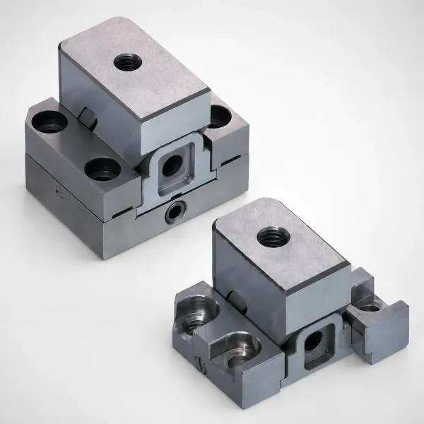
EDM needs no pilot because the electrode defines the position and hardness stops mattering, but it charges a spark account instead of a drill account. Budget 0.01 to 0.02 mm of overcut for the spark gap, plan a recast layer of 1 to 3 microns that you either grind off or keep below the pin contact band, and expect a surface around Ra 0.4 to 0.8 microns from a polished electrode. The economics mirror the hard milling versus EDM comparison: boring buys speed on volume, EDM buys access in deep pockets and odd geometry.
Hard milling with HPC carbide occupies the middle ground. At 48 to 52 HRC, a rigid toolholder, a through-coolant solid carbide drill and a machine with proven 0.01 mm repeatability can cut a dowel pattern to class in the hardened state, with the piloting logic applied by the tool path: center-peck, supported entry, then interpolation. Where the machine cannot prove position, revert to the pre-harden and grind route. A tolerance you cannot measure is one you do not have, and that discipline is the subject of the 0.002 mm tolerance guide.
Assembly Day Checks and Torque
The piloting program earns its money at assembly, where the joint either closes or it exposes every shortcut taken three weeks earlier. Build the check into the assembly sheet as three gates, in order, before any fastener touches a plate.
Gate one is the drop test. With the plates clean and the dowels greased lightly, the pin should start into the lower hole and sink under its own weight through the first 5 to 10 mm as the plates close on guide pins. A pin that stops at the surface means hole positions disagree; a pin that falls through with no drag means the bore was cut loose and the locate is a fiction. Neither condition can be fixed by tightening the clamp screws harder.
Gate two is the flatness check. Seat the joint, then run a 0.05 mm feeler along the parting line and around each insert. A correct piloted pattern closes with the feeler refused everywhere; a gap that takes the gauge at one corner and not the other is a pattern-shift signature, not a burr. Confirm the same flatness with a height gauge on a surface plate before the mold gets its first shim decision. The datum logic behind reading those gaps is the same arithmetic as a written tolerance stack, plate by plate.
Gate three is torque, and it is where good holes still get ruined. Fasten with socket head cap screws at 60 to 70 percent of yield, never by feel. A dry M8 class 12.9 SHCS takes roughly 38 to 45 N m; a dry M10 takes about 75 to 90 N m. Under-torque lets the plates micro-shift each clamp cycle and the dowel edges peen over; over-torque stretches the screw and pulls the plate against the pin until the interference that was 0.02 mm measures as scuffing at the next teardown. Torque values, thread engagement and grade selection are worked in full in the SHCS selection guide.
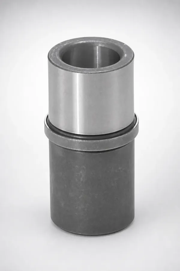
Log the three gates per joint with plate serial numbers. Six months later, when a customer reports flash at one corner of a 500,000-shot mold, the log tells you whether the pattern drifted or the shut-off did, and that distinction is the difference between a half-day grind and a full insert remake.
RFQ Spec for a Piloted Hole Pattern
Most hole rework traces back to a drawing that described the hole but not the program. A machine shop can hold 0.01 mm on a bore and still deliver a joint that will not close, because nothing on the print said which plate the pattern is cut against. Five lines on the RFQ remove that risk, and none of them cost a cent.
Line one names the datum. The pattern is located from the finished ground face, not the sawn side wall, and the print should show true-position callouts referencing that datum. A position tolerance quoted from a wall that carries 0.2 mm of saw variation inherits the variation. Line two states the pattern tolerance itself: what the finished centers may do relative to each other and to the datum, in the two-plate joint sense, not just per plate.
Line three fixes the pin class and the fit. Write the reamed hole allowance and the pin grade, plus 0.01 to 0.03 mm on the bore with an A-3 press-fit pin, so the shop quotes a reamer and a gauge, not a drill pass. Line four marks the entry side: piloting is directional, and a shop that enters from the wrong face burrs the sealing side. Line five states the coolant and hardness condition, because pre-hardened at 280 to 330 HB versus quenched at HRC 50 plus switches the route from reaming to boring or EDM.
Attach a one-page piloting worksheet to the drawing package and ask for it back signed. The worksheet is the six-step table above with three extra columns: actual bore size after reaming, measured position against the datum and the pin gauge serial used. A shop that returns the sheet with numbers has shown you its process; a shop that returns a signature has shown you its confidence, which is worth less.
Putting the Program on the Clock
Piloting sounds slower than drilling, because the first pass through a six-step sequence is. The time lands where it saves: the wander-free hole skips the hand-fit, and the hand-fit is where mold schedules actually die. Price the loop in hours, not in steps.
A dowel position chased by hand fitting consumes 1 to 2 hours per hole: indicate, cut, trial-close, measure, repeat. Four bad dowels on a two-plate joint are two shifts, and a two-shift slip inside a 2 to 5 week tool build is the whole margin between shipping on the trial date and renegotiating it. The piloted cut adds 5 to 10 minutes per hole in center drilling and bushing setup and saves the rework column outright. On a thirty-hole pattern, that trade is a day of machine time against two days of fitting bench, and the machine time does not depend on which of your two good fitters is on shift.
The second clock is the standard-parts calendar. Reamers, pilot bushings and A-3 dowels are catalog items that move in 3 to 7 days when the RFQ names the class on day one. A pattern specified only as drilled and reamed arrives as an argument, the argument waits for a sample pin, and the sample pin waits behind the queue.
Then there is the inspection clock. A piloted, gauged pattern passes first-article measurement in one setup. A drifted pattern fails, gets welded and recut, and re-enters the CMM queue twice. Holding plus or minus 0.005 mm on finished mold geometry means making every hole inherit a datum, not re-measuring holes that never had one.
Piloted Hole Pattern FAQ
Q1. Can I just drill dowel holes on a good machine tool?
Only if the machine proves the joint, not the hole. A rigid CNC with through-coolant drilling holds a 10 mm dowel pattern to 0.02 mm true position in pre-hardened P20 up to about 2.5 times diameter; past that depth the drill wanders 0.1 to 0.3 mm no matter what the positioning system reads. Pilot the entry, ream the finish, measure the joint across both plates.
Q2. What tolerance should a pressed dowel hole hold?
Ream to plus 0.01 to 0.03 mm over pin diameter for an A-3 press fit, giving 0.01 to 0.03 mm interference. H7 with an m6 pin is the machine-shop equivalent. Write the class on the print and gauge with the matching pin gauge, not a micrometer that cannot see roundness.
Q3. How deep can a twist drill go before pecking is mandatory?
Continuous feed is honest up to 3 diameters. Blind holes deeper than 4 diameters need pecks at 1 to 3 diameters with coolant flushing to the bottom, or chip packing will snap the drill in the bore and the extraction time will exceed the drilling time.
Q4. Do dowel holes need pilots after heat treat?
No, because they are not drilled. Bore or plunge EDM the pattern post-hardening; EDM needs no pilot since the electrode defines position, but budget 0.01 to 0.02 mm of spark-gap overcut and a 1 to 3 micron recast layer. Grinding remains the route when the bore class must beat plus 0.01 mm.
Q5. What torque do mold plate screws take?
Torque to 60 to 70 percent of yield: a dry M8 class 12.9 socket head cap screw lands near 38 to 45 N m. Put the value on the assembly sheet next to the dowel drop test so no one closes a joint by feel and blames the pattern for the flash that follows.
The Bottom Line
A piloted hole pattern is a sequence plus a stack, and both are cheap before the steel is cut. Center drill the entry, pilot the drill from the mating plate, run to 90 to 95 percent, then ream to plus 0.01 to 0.03 mm and press the A-3 pin. Call the pattern from the datum face with true position, keep the joint stack inside 0.04 mm, peck past 4 diameters and torque to 60 to 70 percent of yield. Every skipped step becomes a fitting-bench hour later, and fitting-bench hours are how a 2 to 5 week tool misses its trial slot.
DieStrike machines and assembles precision mold and die work to plus or minus 0.005 mm with plus or minus 0.002 mm capability on jig grinding and EDM, HRC 62 heat treat, 120 plus machines and standard components shipping in 3 to 7 days. Hole patterns leave our shop gauged against pin classes, with the worksheet numbers in the tool file.
KEEP READING
Related Reading
Mold GD&T Basics for Buyers
Datum faces, true position and the callouts that tell a shop what a hole pattern must hold.
Read articleArticleHow to Hold 0.002 mm Precision Mold Tolerances
The machine, fixturing and inspection discipline behind two-micron work in mold steel.
Read articleServiceMold Design and DFM Review
Design for manufacturing feedback that flags hole-pattern risk before the program cuts steel.
Read articleNEXT STEP
Ready to Start Your Mold?
Send us your element dimensions or part numbers — our team responds within 24 hours with pricing and lead time.

Written by
Ray ChanMold Buyer's Guide Author · Precision Mold Manufacturing Specialist. Ray helps global importers, distributors and OEMs source factory-direct molds and mold parts.