
How to Prevent Slug Pulling and Slug Rotation in Stamping Dies
Table of Contents
A pulled slug is a small piece of scrap with an outsized bill of materials. On a 200 tonne progressive die running 1.2 mm mild steel, one inverted slug riding back into the die button on the next hit concentrates hardened steel against hardened steel, and the result is a chipped punch, a cracked die block or a split bolster plate. Tooling repair after that crash runs 1 to 3 weeks, because the damaged insert usually has to be remade rather than regrinded, and the line loses 80 to 250 dollars per hour while it waits. This guide shows how slug pulling and slug rotation are prevented as a design problem: clearance held inside 4 to 7 percent per side, shear and step geometry, retainers sized at 5 to 15 percent of the pierce load, and control of magnetism, vacuum and oil adhesion at the punch tip.
The scope is the piercing operation in progressive and stage dies: round, square and oblong slugs from 0.4 to 6.0 mm stock, from first-article trials through million-stroke production.
The Snapshot
- Clearance above 8 to 10 percent per side lets the slug invert. Target 4 to 7 percent per side on mild steel and 7 to 10 percent on stainless, checked at assembly and at every regrind.
- Shear height of 0.5 to 2.0 mm keeps one edge in the die. On a multi-punch blank above 1,500 mm2 of cut section, stagger 3 to 4 steps so no station shears the whole blank at once.
- Retainer force of 5 to 15 percent of the pierce load. A 60 kN pierce needs 3 to 9 kN of downward force on the slug, carried continuously through bottom dead centre and the first 10 mm of punch retract.
- Repair window of 1 to 3 weeks. A slug-crashed die button cannot be saved by grinding; the insert is remade, and standard tooling components ship in 3 to 7 days only if they are on the spare list before the crash.
What Slug Pulling Costs a Stamping Line
The mechanism of damage is simple. The punch retracts with the slug stuck to its tip or underside, the strip advances one pitch, and the next stroke drives punch plus slug into a die opening that is sized for the punch alone. A 0.5 mm sliver of trapped steel between a punch and a die land multiplies the local pressure past the compressive limit of tool steel, and the first thing to fail is the part with the thinner section: usually the die button edge, then the punch tip, then the bolster under the shoe.
Costs stack in three layers. The direct layer is tooling: a wire-cut and ground die insert runs hundreds of dollars in shop cost, but the lead time to remake it is 5 to 10 working days, and a cracked bolster or upper shoe is 2 to 3 weeks of machining and welding repair. The second layer is production: at 80 to 250 dollars per hour of downtime, a three-day outage on a two-shift line is 4,000 to 6,000 dollars before a single replacement part ships. The third layer is quality debt: a press that ran 500 strokes with a lightly pulled slug produces parts with a secondary shear band and 0.05 to 0.15 mm positional shift, and containment of those parts costs more than the crash would have.

Slug pulling also has a slow, invisible form: rotation. When a slug spins a few degrees inside the die land before falling, the punch edge rubs the land on the way down and the way up. That rubbing widens the opening by a few hundredths of a millimetre per 100,000 strokes, doubles the burr, and moves the station into an accelerated clearance spiral. The punch clearance maintenance guide covers the regrind side of that spiral; this article covers the slug dynamics that start it.
Treat every pull event, visible or micro, as an unplanned stop that has not happened yet. A die at 400 strokes per minute that pulls one slug in twenty thousand hits is a statistically guaranteed crash inside a month.
The Five Mechanisms That Pull a Slug
Slug pulling is five different physical mechanisms wearing one symptom. Fixing the wrong one wastes the shutdown, so classify the event before you change the die.
1. Excess clearance and inversion. Piercing separates by two crack fronts meeting. At 4 to 7 percent clearance per side the fracture surfaces stay short and the slug leaves the land square. Pushed above 8 to 10 percent per side, the secondary shear band grows, the slug belly bulges and can tip inside the land; on the punch retract it presents a corner to the land edge instead of a flat face, catches, and rotates or lifts. Inversion is the dominant mechanism on worn dies and on holes punched near the high end of the clearance band.
2. Adhesion at the punch tip. Stamping oil is held on the punch nose by surface tension. Pulling a 6 mm diameter punch out of an oil film needs roughly 1 to 2 N, which sounds trivial until you add the vacuum effect below; adhesion plus suction together grip a 0.5 kg slug against nothing but gravity and a weak stripper. Viscous oils at 10 to 20 weight, cold shop mornings and flooded spray stations all raise the grip. The fix is not dry punching: it is metered, low-viscosity lubricant and a stripper or retainer that beats the film force.
3. Magnetic grip. Grinding, wire EDMing in some dielectrics and contact with chucks leave residual magnetism in punch tips. A magnetized tip holds slug steel against stripper pressure; fields of a few gauss at the tip are enough to walk a 3 mm slug up a 30 mm punch land inside the first hour of a shift. New or re-ground punches are the usual suspects, and an uncontrolled grinding room is a slug-pulling factory.
4. Vacuum in a tight land. A punch nose that runs tight to a die land, with land height over 0.15 to 0.25 mm at under 3 percent clearance per side, works like a piston. Air cannot get under the slug fast enough, the pressure difference of about 0.1 MPa across the slug top pulls it along, and a 10 mm slug sees around 8 N of suction. Counter-intuitively, this is a too-tight problem, not a too-loose one, and it shows up on precision stations that the team believes are conservatively ground.
5. Pilot and strip-lift timing. If the pilots leave their holes late, or the stock lifters are slow to drop, the strip lifts with the punch. The strip edge drags the partly-cut slug against the land, and slug and strip both climb. The event correlates with feed speed and pitch rather than with clearance, and the diagnosis belongs with the strip feed accuracy guide: pilot entry should lead punch penetration by 10 to 20 milliseconds or 2 to 4 mm of cam travel at 200 strokes per minute.

The five mechanisms add. A die at 9 percent clearance with a magnetized tip and a flooded oil station will pull slugs even though each single factor looks survivable alone. That is why the sections below set all four independent controls, not one.
Piercing Clearance: The 4 to 7 Percent Window
Clearance is per side, as a percent of stock thickness, and it is the first control because it sets whether the slug leaves square or leaves a lever. On mild steel up to 350 MPa tensile, run 4 to 7 percent per side: 4 to 5 percent on stock under 1.0 mm where edge strength is scarce, 6 to 7 percent above 2.0 mm where the fracture wants room. On 300-series stainless with work hardening above 500 MPa, run 7 to 10 percent because the slug necks and rubs instead of snapping clean. Aluminium 5052 sits back at 3 to 6 percent, and spring strip above 40 HRC needs the tight end plus a coating or it abrades the land.
The failure band is asymmetric, and both edges pull slugs. Above 8 to 10 percent per side, inversion and rotation take over: the slug tilts inside the land, and the corner catch on retract starts the event. Below 3 percent with a land over 0.20 mm, vacuum grip and secondary shearing take over, and the slug clings to the punch. The mid-band is narrow on purpose: a 12 mm hole punched in 1.5 mm stock at 5.5 percent per side carries 0.165 mm of total diametral slack, and 0.01 mm on the wire path is 6 percent of that window.
| Material | Clearance per side | Land height | Pull failure if wrong |
|---|---|---|---|
| Mild steel, 1.0 to 2.0 mm | 5 to 6 percent | 0.10 to 0.15 mm | Above 8 percent: inversion and rotation in the land |
| Mild steel, 2.5 to 6.0 mm | 6 to 7 percent | 0.15 to 0.25 mm | Secondary band grows, slug bellies and tips |
| 300 series stainless | 7 to 10 percent | 0.10 to 0.15 mm | Work-hardened slug grips the punch and climbs on retract |
| Aluminium 5052-H32 | 3 to 6 percent | 0.05 to 0.10 mm | Galling film plus vacuum, slug sticks to a dry punch |
| Brass and copper | 4 to 7 percent | 0.05 to 0.10 mm | Clean cut, but oil adhesion dominates on small holes |
| Spring strip above 40 HRC | 3 to 5 percent | 0.08 to 0.12 mm | Land abrasion opens clearance into the inversion band by 200k strokes |
Table note: clearance bands are typical shop values for punching at 100 to 400 strokes per minute with a coated die button and a pilot-guided strip. Confirm against the incoming coil certificate and the burr height measured on the first-off before releasing the electrode program.
← swipe to scroll →
Two design details keep the window honest over tool life. First, put the clearance on the punch, not the block: the punch wears and is cheap to remake, the die button is not. Second, plan for the regrind. Every die-face grind lowers the land entry; after 0.30 mm of cumulative regrind a 0.15 mm land is gone and the station behaves like a zero-land die, which pushes it toward the vacuum-grip failure instead of the inversion failure. The die regrind schedule should carry per-station land height so clearance drift is a number, not a surprise.
Shear and Step Punch Geometry
Shear on the punch does two jobs at once: it cuts peak tonnage, and it changes the slug exit from a single snap into a progressive sweep. A ground-in shear height of 0.5 to 2.0 mm across the punch nose makes the fracture initiate at one edge and travel, so the slug pivots down out of the land instead of being jolted straight down. The tilt force on the slug drops, the punch unloads over a longer and softer stroke, and the land never sees the full shock of a flat shear.
The sizing rule: shear of 25 to 33 percent of stock thickness per side on large profiles, capped at 2.0 mm on through-hardened punches, and never enough shear to pull the punch tip out of the stripper guide at top of stroke. On a 3.0 mm blanking punch, 0.75 to 1.0 mm of shear is the standard cut. On 0.8 mm stock, a 0.2 to 0.3 mm shear still removes 20 to 30 percent of peak load and helps small slugs rotate cleanly through the land instead of hanging.
Step punches extend the same logic across multi-punch blanks. On a blank cut by four corner punches plus a profile, stagger the tips in 0.5 to 1.0 mm steps so that at bottom dead centre at least one edge is still inside the die while the others have exited. The design check is one sentence: at every point of the retract, some part of the cut must stay supported inside a land. Simultaneous full-perimeter cuts on large blanks are the geometry most likely to belly a slug and let it stand up in the pocket.

Perforator selection interacts with shear. A clustered round perforator with integral shear, an internal slug relief and a carbide blade is the factory answer to slug pulling on hole fields, and the geometry, land and force rules are in the perforator selection guide. The one-line version: specify through-ground, vented pockets, and prefer cartridges whose blade is designed to break past the slug rather than to seal the pocket into a vacuum trap.
Slug Retainer Families and Applied Force
A slug retainer is any device that holds the slug below the die face while the punch retracts, or sweeps it out sideways. The sizing rule is common to all of them: applied force of 5 to 15 percent of the pierce load, directed on or beside the slug, continuous from just before bottom dead centre to at least 10 mm of punch retract. For a 60 kN station that is 3 to 9 kN; for a 5 kN fine perforator cluster, 250 to 750 N. Under 5 percent the retainer loses to combined adhesion and vacuum; over 15 percent it drags the slug edge across the land and you have bought rotation wear.
- Spring plungers. Hardened tips, 6 to 20 mm diameter, 15 to 300 N each, mounted beside or through the land edge. The default for holes 6 mm and above: two opposed plungers on a 12 mm slug deliver roughly 10 percent of pierce load, and 1.5 to 3.0 mm of travel keeps them active while the strip lifts. Coil relaxation of 10 to 20 percent by 500k strokes makes plunger force a PM measurement, not an assumption.
- Urethane rings and pads. Polyurethane at 90 to 95 Shore A machined over the pocket floor, cheap, quiet and force-progressive: a 20 mm ring gives 50 to 200 N at 1 to 2 mm deflection. Use them on hole clusters below 5 mm where steel plungers collide, and replace at visible compression set, typically every 200k to 500k strokes.
- Knife and blade retainers. A hardened edge across the pocket that the slug breaks past going down and cannot climb going up. Holding force reaches 10 to 20 percent of load because the slug edge deforms slightly at the blade. The standard answer on sticky stainless slugs, and a 0.2 mm carbide blade on a cartridge perforator is already one.
- Side-exit cutters. The land becomes a slot with 30 to 45 degrees of lateral relief and the slug exits sideways into a chute. No holding force is needed because the pocket stops existing; gravity and the next hit clear the path. Noise, chute plugging and slug orientation downstream are the price.
- Air blast. A 1 to 2 mm nozzle into the pocket firing 0.2 to 0.5 MPa for 20 to 50 ms after bottom dead centre puts 2 to 10 N on the slug face, enough to beat adhesion and vacuum on slugs lighter than 2 g and useless against a magnetized tip or an inverted corner. Treat it as a helper on small holes and a pocket cleaner everywhere, and filter the airline to a 5 micron coalescer because oil carryover is its own adhesion source.

Retainers fail in three ways, all preventable at drawing stage. The tip wears a groove beside the slug path and stops touching the face: keep tips 0.5 to 1.0 mm inside the pocket edge and inspect the contact pattern at every PM. The spring fatigues below the 5 percent floor: record plunger force in newtons at each service. Swarf packs the bore and freezes the plunger up: vent the pocket and never let a retainer share a sealed pocket with no debris relief.
Punch Pockets, Retaining Punches and Relief Design
The punch side carries its own slug dynamics: the strip climbing onto the punches, and slugs stuck to the punch face above the stripper plate. Both are pocket-design problems before they are press problems.
Where punches screw or clamp into the upper shoe, mill a clearance recess around the shank at least 1.5 times the stock thickness deep, and drill the pocket floor through to atmosphere. A punch running in a blind, snug pocket works as a pump: each retract stroke pulls a partial vacuum between punch face and pocket roof, and that pressure difference is what lifts the strip and drags the half-cut slug with it. Clamping-plate retention beats threaded retention on fine pitch because the plate stands punches apart and every pocket opens to the side channel at once.
For punches 0.4 to 2.0 mm in diameter, a shouldered or ball-lock retaining style stops the punch walking up with the strip even when suction is present: the retention shoulder carries the pull instead of the threads. Under the stripper plate, run punch clearance at 1 to 2 percent per side on steel punches and 0.02 to 0.05 mm per side on carbide; looser and the stripper skin catches slug edges, tighter and the punch itself adds to the vacuum piston.
Give every punch land a top-of-pocket vent or a wire-EDM through-hole to atmosphere, even 0.5 mm. That single vent path is the difference between a suction cup and a plain punch, and it costs one line on the drawing.
Gravity Drop Versus Lateral Slug Eject
Below the land, the slug has to leave. The default answer is gravity: a pocket that drains straight down, with plan area at least the slug's largest cross-section plus 1 mm per side, and enough stack clearance for the first slug to fall 20 to 40 mm below the bottom face before the next one lands on it. Gravity fails quietly in three situations worth designing around. Slugs smaller than roughly 1.5 times stock thickness in characteristic size do not outweigh adhesion and air drag. Pockets that bridge with interlocking slugs once the bin fills at 5 to 10 mm of pile. And presses running at an angle or inverted, where down is not where the pocket points.
For those cases the answer is a lateral path: a slot land with 30 to 45 degrees of side relief sending the slug into a chute, or a cam-driven side kicker on lines above 500 strokes per minute. The slug exits horizontally to a conveyor running 0.1 to 0.3 m per second and the vertical pocket stops existing. Slope every chute 5 to 10 degrees and fit a clean-out port every 500 mm, because a plugged chute turns a gravity design back into a crash: slugs back up into the pocket and the next hit shears steel on steel.
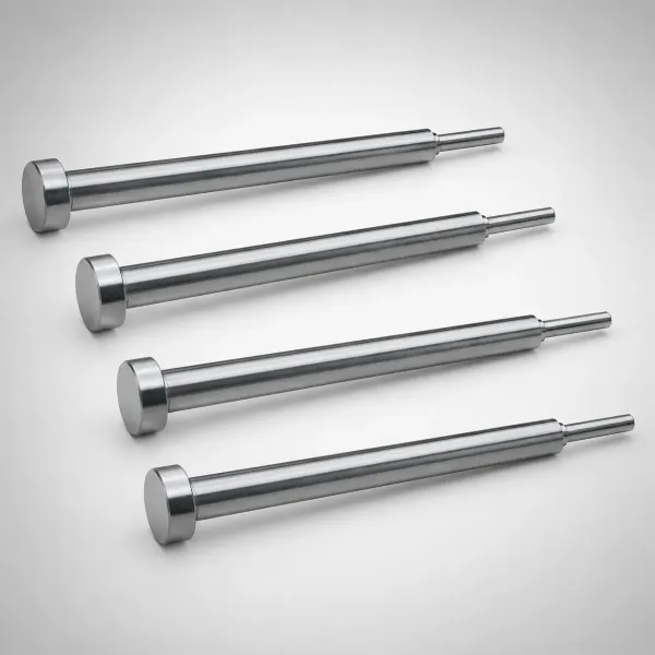
Scrap routing rule of thumb: a slug falls cleanly when its smallest plan dimension exceeds about 1.5 times the stock thickness; below that ratio, burr, oil and static keep it dancing in the pocket. On a terminal die running 1.0 mm stock with 1.2 mm pilot and vent holes, every small hole sits under the ratio, so those stations get perforators with integral slug control as a drawing note, not a post-T1 rescue. Document the chosen family per station on the die card so the press team knows which pockets are gravity, which are retained and which are side-exit.
Magnetism, Vacuum and Adhesion Control
Residual magnetism is measured, not assumed. Every punch tip and retainer tip coming off the grinder gets a Hall-probe check at the nose: above 2 gauss, demagnetize before assembly; above 10 gauss, stop the batch and find the process cause at the machine. An AC demagnetizer withdrawn 300 mm at a slow retreat takes hardened steel to under 1 gauss in seconds. Grinding-chuck transfer is the common source, and the fix is a degaussing station at the grinder rather than triage at the die. Re-check tips after every regrind, because grinding re-exposes subsurface steel that never saw the first pass.
Vacuum is controlled by geometry: land height at or under 0.15 mm on holes below 6 mm, pocket vents as specified above, and clearance never pushed under 3 percent per side as a false economy for edge life. Where a precision application forces a tight land, the timed air blast covering 20 to 50 ms past bottom dead centre cancels the remaining suction on slugs under 2 g.
Adhesion is a lubricant-discipline problem. Metered application beats flooded spraying: target 2 to 5 ml per square metre of strip on fine hole fields, a light film on general piercing, and a 10-weight or dry-film lubricant wherever holes run near 3 percent clearance and suction already conspires. Cold shop mornings roughly double oil viscosity, which is exactly when sticky-slug complaints appear at random; hold oil and strip at 18 to 25 degrees C at the press and record the lubricant grade on the die card so a lube change is a logged event instead of an unsolved mystery.
Monitoring: Tonnage Signature and the PM List
A slug on a punch tip is a second shear event in one stroke, and the press load curve sees it before anyone else. Normal piercing shows a ramp to a single peak at about 60 to 75 percent penetration and a clean drop at fracture. A slug riding the punch adds a second bump of 10 to 30 percent of peak load 1 to 3 ms after the drop, or shifts the peak itself above the band. Set the tonnage monitor at 110 to 120 percent high and 70 to 80 percent low against a validated signature that repeats within 5 percent over 20 strokes, and alarm on the double-hit shape, not only the amplitude.
Acoustic monitoring sharpens the same signal: an accelerometer on the bolster with a band pass at 2 to 8 kHz hears the metallic tick of a slug contacting a land, and a die at 300 strokes per minute will log the event long before a crash. Sensor channels, placement and the reaction window inside a 100 ms stroke are covered in the die protection sensors guide; the slug-specific addition is one sensor or one camera aimed at the busiest deep-pocket station rather than only at the strip path.
Then close the loop on the maintenance side. The PM list earns a permanent slug-control block: field-check punch tips with the Hall probe every regrind; measure spring plunger force and replace coils past 15 percent relaxation; inspect urethane rings for compression set at every 100k-stroke service; clear and sight every chute and pocket; count slugs in the bins against a holes-per-strip calculation, because a bin running 5 percent short on 200 hole parts is a pocket inventory nobody has found yet. A pulled slug that stays inside the tool for ten thousand strokes is not a near miss; it is a crash on a timer.
Failure Pattern Map: Symptom to Cause
Use the pattern on the steel to pick the mechanism, then apply the matching control. The map below assumes the strip is fed correctly and shut height is set to the die card.
| Observed pattern | Lead cause | Confirming check | Control to apply |
|---|---|---|---|
| Slug round, edge corner chamfered 0.2 to 0.5 mm | Rotation in the land, clearance high | Measure clearance; above 8 percent per side | Re-grind to 5 to 6 percent, add opposed plungers |
| Slug stuck to punch tip, no corner damage | Magnetism or adhesion | Hall probe at nose; wipe dry and retest | Demagnetize to under 2 gauss, meter the oil |
| Small holes pull, large holes run clean | Vacuum and oil grip beat slug weight | Slug under 1.5 times stock thickness | Perforator cartridge, side exit or air blast |
| Strips lift with the punch at 3 to 5 stations | Blind punch pockets pumping air | Punch face shiny ring, pocket no vent | Vent pockets, stripper force to 10 percent of load |
| Event follows coil lot change only | Hardness spread opens the fracture band | Hardness and tensile from the certificate | Shift clearance 1 percent per side, re-trial |
| Crash at shift start, clean after warm-up | Cold oil viscosity doubles film force | Shop under 15 degrees C at first hour | Lower-viscosity grade, warm the strip line |
Table note: the map pairs field symptoms with the mechanism tests used at the press side. Any two patterns appearing together means two mechanisms are active, and both controls belong in the same shutdown.
← swipe to scroll →
The Bottom Line
Slug pulling is five separate mechanisms with one crash outcome, so the prevention stack sets all four independent controls at once. Clearance lives at 4 to 7 percent per side on mild steel and 7 to 10 percent on stainless, because both 3 percent vacuum grip and 8 percent inversion pull slugs. Shear of 0.5 to 2.0 mm and 3 to 4 step punches keep one edge in the die through the whole retract. Retainers of the right family carry 5 to 15 percent of the pierce load from bottom dead centre through 10 mm of lift. And magnetism under 2 gauss, vented pockets and metered oil remove the invisible grip that defeats the other three.
The verification is just as numeric: a tonnage signature repeating within 5 percent over 20 strokes, a bin count that matches holes per strip, and a PM list that measures plunger force and probe field instead of trusting them. Build those checks into the tool file from the first trial, and the 1 to 3 week repair window stays where it belongs: in the budget line you never spend.
DieStrike builds progressive and stage dies to IATF 16949 with +/-0.005 mm mold tolerance, +/-0.002 mm on EDM and jig-grinding, hardened tooling up to HRC 62 and a 120+ machine park. Tool lead times run 2 to 5 weeks, standard components ship in 3 to 7 days, and tier-one programs at TE, Amphenol, Luxshare and Dongshan ride on die cards that record slug control per station.
KEEP READING
Related Reading
Die Protection Sensors in Progressive Dies
Sensor families, placement after the feeder and the timing budget inside a 100 ms stroke.
Read articleArticleHow to Set a Die Regrind Schedule
Burr height limits, regrind depth per pass and the shot-count trigger that keeps cutting edges honest.
Read articleArticleHow to Design Stamping Die Strippers
Stripper clearance, urethane versus coil springs and the hold-down force that keeps the flat from lifting.
Read articleServiceStamping Die Manufacturing
IATF 16949 progressive die building with slug control designed in and 2 to 5 week lead times.
Read articleNEXT STEP
Ready to Start Your Mold?
Send us your element dimensions or part numbers — our team responds within 24 hours with pricing and lead time.

Written by
Ray ChanMold Buyer's Guide Author · Precision Mold Manufacturing Specialist. Ray helps global importers, distributors and OEMs source factory-direct molds and mold parts.