
How to Select a Hydraulic Fixture for Mold and Die Trial
Table of Contents
A 4 t stamping die rode half a millimeter off its locating blocks on the first hit of a trial. A torque wrench on four T-slot bolts is not a clamping plan. The die walked and the first-off parts were scrap. The schedule lost two days to a re-set a hydraulic clamp at 180 bar would have held in seconds.
This guide sizes the fixture for an injection mold face and a stamping die face. Then it compares the clamping hardware that holds each one still.
The Snapshot
- Force against projected area. An injection mold face needs 5 to 6 MPa of projected area. A 600 by 400 mm face at 6 MPa needs roughly 144 t of holding force.
- Hydraulic cylinders cut set-up. A single-point clamp cylinder delivers 30 to 90 kN at 200 bar and drops corner set-up from 15 to 30 minutes down to 2 to 5.
- Zero-clamp change under 10 minutes. Roll-in zero-clamp systems cut a mold change from 60 to 90 minutes to under 10, and you pay for it in table prep and H7 alignment pins.
- An unclamped die is 3 to 10 t in motion. Back every hydraulic circuit with an accumulator so a hose failure does not release the die mid-stroke.
How Much Clamping Force the Mold Actually Needs
Clamping force is not a comfort number. It is the force that keeps the mold halves or die faces closed against the machine load. The size of that load comes from the projected area and the pressure behind it. Get this arithmetic wrong and no clamp, hydraulic or otherwise, saves you.
On the injection side the rule of thumb is 5 to 6 MPa of projected part area. Multiply projected area by cavity pressure to get the separating force. A 600 by 400 mm mold face projects 240,000 square millimeters. At 6 MPa that face needs roughly 144 t of holding force.

On the stamping side the logic shifts. The clamp does not fight cavity pressure; it fights the cutting and forming reaction. A practical margin is 30 to 80 percent of press capacity as available force.
The fixture must resist the shear load, not just the vertical lift. A 200 t press blanking a high-strength grade can push several tons of lateral force into the die. A clamp layout with no back-side stop takes none of it.
Add one more margin on top of the computed force. Hydraulic fixtures leak a little at every fitting and every seal. Sizing the circuit at exactly the theoretical load leaves no reserve when the first gauge weep appears. A working trial habit is to design for the computed force and prove the circuit at 120 percent of it during set-up.
Also check the force against the weakest element in the chain, not the strongest. A 90 kN cylinder bolted to a mold base tapped for M12 bolts is only as strong as those bolt roots. The clamp, the bolt, the step and the table slot form one series. The lowest rating wins, and that rating belongs in your worksheet.
Two numbers belong on the fixture request before hardware is chosen. Give the projected area in square millimeters and the peak process force in kilonewtons. Where the area estimate disagrees with a live cavity-pressure reading, trust the reading. The clamp tonnage method puts those inputs on one sheet, so the fixture and the machine size against the same target.
The Four Clamping Styles Compared
Every trial fixture falls into one of four families. Cheap manual work, hydraulic clamp cylinders, a full press-supplied hydraulic die set, or a chuck that holds the mold back flat. The choice trades set-up time against holding force, capital cost and how flat your mold back already is.
| Clamping style | Set-up per corner | Force range | Cost index | Best use |
|---|---|---|---|---|
| T-slot and step clamp | 15 to 30 min | Torque wrench dependent | 1 (lowest) | One-off trial dies, low volume |
| Hydraulic clamp cylinder | 2 to 5 min | 30 to 90 kN at 200 bar | 3 | Repeated trials, mixed molds |
| Press hydraulic die set | 3 to 6 min | Gauge-read, press supply | 6 | High-cycle presses, big dies |
| Magnetic or vacuum chuck | Under 2 min | 200 to 400 N per sq cm | 8 | Flat-back molds on ground plates |
← swipe to scroll →
Table note: set-up times and force bands are typical trial-shop values. Confirm against your press data sheet and the mold back condition before you commit to a fixture family.
A T-slot and step clamp is the honest default for a die set once. It costs almost nothing and works everywhere. But the clamp force is only as good as the bolt torque and the step height you chose.
A hydraulic clamp cylinder buys repeatability. You set the gauge once and every corner returns to the same force. A press-supplied die set removes the loose cylinders and reads the force from the machine. A magnetic or vacuum chuck is fastest but needs a flat, ground back.
The decision is not which style is best. It is how many mold changes the trial program runs. A shop changing three molds a day buys minutes that a single-die trial never recovers. A shop setting one die for a 50-shot shutdown buys nothing with speed and should spend nothing on it.
Count the changes before choosing. Multiply the mold-change frequency by the set-up gap in the table above, then price the difference at your press hourly rate. That arithmetic, not preference, decides the fixture family on most trial programs.
Hydraulic Clamp Cylinders: Sizing and Layout
A single-acting hydraulic clamp cylinder is the workhorse of the trial fixture. Bore sizes commonly deliver 30 to 90 kN of clamping force at 200 bar. That force arrives at a known value the moment you read the gauge. A torque wrench cannot promise that. A 90 kN cylinder holds about 9 tons at each station.
Layout matters more than count. Put the clamps where the process force is highest. On an injection mold that means opposite the gates and along the long sides. On a stamping die it means the cutting corners plus a lateral stop.
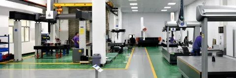
Keep clamp pitch between 150 and 300 mm so the plate does not deflect between points. Never place a clamp where the ejector stroke or runner pull needs the room later. Set the cylinders to pull the mold onto the table and push it into the back stop, not just down.
Vertical clamps alone hold the mold against lift and let shear walk it sideways. A layout that fights the process force is a fixture. One that only bolts the plate down is a hope.
On set-up, a single hydraulic circuit with a manifold drops corner time to 2 to 5 minutes. A torque wrench takes 15 to 30. That gap compounds across a trial with many tool changes.
Two habits quietly ruin hydraulic clamping. The first is over-height steps that let the mold lift before the clamp loads, which turns a set-up into a live load. The second is running every clamp off one gauge without checking the end stations for leakage. One weeping hose then lowers the force across the whole mold with no visible alarm.
Press-Supplied Hydraulic Die Set Systems
A press-supplied hydraulic die set pipes the press's own oil into clamp channels built into the platen. The practical benefit is that clamping force reads from a gauge on the press panel. The operator sees the number as part of the machine, not as a bolt-on. For a trial with high cycle counts or heavy dies, that integration is worth the capital.
These systems pair naturally with a die set that carries its own accumulator. When the press oil pressure dips, a trapped accumulator volume holds the clamp at setpoint. Force on platen-fed systems commonly reaches several hundred kilonewtons per circuit. That is well beyond a small cylinder bank, and one dial controls it.

The trade is flexibility and cost. A platen-fed layout is machined for a specific table and bolt pattern. It moves between presses poorly and costs roughly six times a manual T-slot fixture. In a shop that runs one die across three presses, a bolt-on hydraulic cylinder set that travels with the die is the smarter buy.
Before you specify a platen-fed set, confirm the press already has the clamp circuits and the accumulator option. Many presses ship with a hydraulic supply sized for the ram, not the table clamps. Adding a dedicated clamp loop is a machine-side job, not a fixture job.
The Safety Discipline of an Unclamped Die
The reason a hydraulic fixture earns its cost is not convenience. An under-clamped die is a falling object. A mold dropped from an unclamped tilt is 3 to 10 tons of steel in motion. The clamp is the last thing between that mass and the floor or a technician.
Three rules hold the line. Clamp on the machine-side rail or use dead-stop brackets so the mold cannot tip toward the open side. Never clamp outside the table slots, since a step bridging unsupported table is a bending load the fixture was not rated for. And back every hydraulic circuit with an accumulator. A hose that bursts mid-stroke releases a clamp held only by live pump pressure.
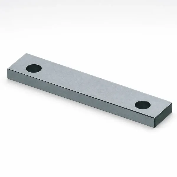
Test the release behavior, not just the hold. On a fixture with an accumulator, shut off the pump and watch the gauge. A clamp that holds setpoint for a full stroke with the pump dead is safe. One that bleeds toward zero over a few cycles hides a hose or seal fault.
The rigging discipline carries through to the trial table. Same rated slings, same clear-zone habits, and the die clamped before the lifting hardware comes off. The rigging and storage method is the same one you would use while the die hangs from the crane. Do not run a stroke until the clamp is proved under load and the lateral stop is confirmed with a feeler.
Quick-Change and Zero-Clamp Systems
The fastest fixture is the one you barely clamp. A zero-clamp quick-change system pairs a roll-in cart or table-lift with clamp rails that grab the mold base as it seats. It cuts a change from 60 to 90 minutes down to under 10. On a trial with frequent swaps, six changes a day at ten minutes beats two changes at ninety.
The cost is hidden in the table, not the cart. Zero-clamp needs the machine table prepared with clamp rails at a fixed pitch. It needs the mold base machined to match, with H7 alignment posts so the die lands in one shot. A mold base drilled to a different post spacing will not seat, and re-cutting it is a tool-shop job, not a trial-day job.
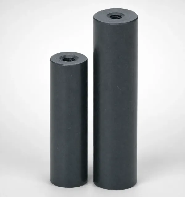
The alignment pins carry the real load in a zero-clamp layout. The clamps hold the mold down; the pins locate it. A worn or oversize post lets the die shift the moment the press hits. The quick-change mold design method covers that base-side geometry. It includes the draft and shut-off clearances the posts must clear each cycle.
Do not overspend on speed the trial does not need. A one-off die set for a 50-shot shutdown does not justify a zero-clamp table conversion. The payback appears only when changeover count, not changeover speed, drives the schedule.
The Fixture Sizing Worksheet
A fixture chosen from a worksheet is a fixture that fits the first time. The worksheet has six lines. Each is answered with a number you can read off the machine or the mold. Each line that stays blank becomes a surprise on trial day.
| Worksheet line | What to record | Why it decides the fixture |
|---|---|---|
| Mold mass | Total kilograms or tons | Sets lifting gear and minimum clamp hold |
| Press daylight | Min and max shut height in mm | Mold plus platen must fit the window |
| Table size | Width by depth and slot pitch | Bounds the clamp footprint and pitch |
| Clamp pitch | 150 to 300 mm spacing | Keeps plate deflection between points low |
| Required force | Projected area times process pressure | Sizes cylinder count and bar setting |
| Pull space | Ejector and runner stroke room | Keeps clamps clear of the ejection zone |
← swipe to scroll →
Table note: fill each line from the press data sheet and the mold drawing. A fixture built against six blank lines is the reason a die sits on the floor for a day.
The two lines most often missed are daylight and pull space. A mold that clamps perfectly but exceeds the shut-height window cannot reach a dead stop. A clamp parked in the ejector travel path turns the first ejection into a collision. Both are fixture-layout failures, not mold failures.
Check daylight and table fit against a full list before you buy. The machine compatibility checklist runs twelve dimensional checks. Shut height, daylight, tie-bar spacing and clamp stroke confirm a fixture and mold occupy the same press.
Trial-Day Checklist
A fixture is only proven on trial day, when the press is live and parts are coming off. Run this sequence top to bottom before the first full-speed stroke. Do not skip a line because the last tool looked fine.
- Read the gauge cold. With the pump off, confirm clamp pressure holds setpoint for one full minute and does not bleed.
- Feeler the back stop. Verify zero gap between the mold back and the stop, and a 0.05 mm feeler will not pass.
- Confirm first and last station. Check force at the extreme clamps, not just the manifold gauge, so a weeping circuit is caught.
- Clear the ejector path. Hand-cycle one slow stroke and watch the ejector and runner pull for clamp interference.
- Kiss the shut height. Bring the die to contact at low speed and confirm no lift before the clamp took the load.
- Log against the golden sample. Measure the first-off parts and file the numbers with the fixture settings.
The checklist is short on purpose. A long procedure does not get run at 6 a.m. on the first shift. Where the trial feeds a formal sampling run, fold the clamp settings and first-off numbers into the T1 report. A fixture proven once is then documented for reuse.
A supervised trial service captures that same data against the dimensional report and the shutdown plan. The clamping record then joins the tool file. The next run of the same mold starts from a proven setting instead of a fresh guess.
What to Send Your Fixture Maker
Most fixture mistakes are made before the metal is cut, in an RFQ that left out a number the maker needed. A clean fixture spec sheet is short and complete. Send these items and a competent fixture shop returns a working design. Send fewer and it returns questions.
- Machine make and model. The press vendor and model, so the maker knows table slots, oil supply and clamp options.
- Shut height and daylight. The working shut-height range and the daylight window, in millimeters.
- Table size and slot pitch. Width, depth and slot dimensions, so clamp rails and steps are cut to fit.
- Mold weight and projected area. The total die weight in kilograms and the projected area in square millimeters.
- Required clamping force. The computed force in tons or kilonewtons, with the process pressure you assumed.
- Cycle time target. The changeover and cycle target, which decides manual, hydraulic or zero-clamp.
Give the maker the pressure you assumed, not just the force number. A fixture sized to a 5 MPa injection assumption behaves differently under a stamping shear load. A maker who sees the assumption can challenge it.
This is the same RFQ hygiene that makes a mold quote comparable across suppliers. The fixture spec is a mini-RFQ, and it fails the same way when a line stays blank.
Where the fixture is part of a tooling package, not a separate purchase, the clamping interface belongs in the mold design review. It does not belong in a bolt-on after the die is cut. Bringing the fixture decision into design for manufacture keeps the clamp layout and the ejector path from fighting over the same square millimeters of table.
Hydraulic Fixture FAQ
Q1. How much clamping force does a mold need?
On an injection mold, 5 to 6 MPa of projected part area. A 600 by 400 mm face at 6 MPa needs about 144 t of holding force. On a stamping die, size the clamp against the cutting and forming reaction, often 30 to 80 percent of press capacity.
Q2. Why choose a hydraulic clamp over a T-slot?
Repeatability and speed. A hydraulic cylinder delivers 30 to 90 kN at 200 bar, at a force you read from a gauge. It drops corner set-up from 15 to 30 minutes down to 2 to 5. A torque wrench gives whatever the last technician gave it.
Q3. What is zero-clamp and when is it worth it?
A roll-in cart and clamp-rail system that grabs the mold base as it seats. It cuts a change from 60 to 90 minutes to under 10. It pays off when changeover count is high and the bases use H7 posts. A one-off die does not justify the table conversion.
Q4. Why does a hydraulic fixture need an accumulator?
Because live pump pressure is not a safety device. A hose that bursts mid-stroke releases a clamp held only by that line. An accumulator holds setpoint when the pump drops, so the die stays clamped when the pressure source fails.
Q5. Can a magnetic chuck hold a mold on a press?
Only a flat, ground-back mold. A magnetic or vacuum chuck develops 200 to 400 N per square centimeter against a true surface. A mold with a warped back or feet loses contact and loses grip.
The Bottom Line
A hydraulic fixture is a force calculation first and a hardware choice second. Size the clamping force against projected area and process pressure. Pick the family by changeover count, not preference.
Never let comfort override an accumulator and a tested lateral stop. The mold that walks off its locating blocks did not have the wrong clamp. It had no number behind the clamp.
DieStrike builds precision molds and stamping dies to IATF 16949 on 120+ machines to ±0.005 mm. EDM and jig-grinding work holds ±0.002 mm, and heat treat reaches HRC 62. Standard components ship in 3 to 7 days and tool lead times run 2 to 5 weeks. Stamping dies run on our own presses; injection and die-casting trials run supervised. Send the projected area and the machine model and we will return a clamping plan before the tool is cut.
KEEP READING
Related Reading
How to Design Molds for Quick Change: SMED Tooling and Base Systems
Clamp bases, alignment pins and roll-in carts that cut mold change from an hour to minutes.
Read articleArticleHow to Die Set a Progressive Die: Shut Height, Feed and First-Off
The die-side sequence a fixture must hold still: shut height, strip feed and first-off parts.
Read articleArticleHow to Run a Mold Trial: T0, T1, T2 and First Article Approval
What the trial must prove once the tool is clamped, measured and shooting.
Read articleServiceMold Trial and T1 Sampling
Supervised T1 trials under an IATF 16949 quality system with clamping, shutdown and dimensional reports.
Read articleNEXT STEP
Ready to Start Your Mold?
Send us your element dimensions or part numbers — our team responds within 24 hours with pricing and lead time.

Written by
Ray ChanMold Buyer's Guide Author · Precision Mold Manufacturing Specialist. Ray helps global importers, distributors and OEMs source factory-direct molds and mold parts.