
PEI (Ultem) Injection Molding: High-Heat Material Guide
Table of Contents
Trial 3 of a 16-cavity Ultem connector mold stalled with 12 of 16 cavities short at the mounting boss. The gate insert ran at 188°C against a 150°C target, and flow stopped 60 mm short of full fill on every shot. The tool was built for a nylon program: water cooling, standard vents, and a small gate. The resin was fine. The mold was designed for the wrong processing window, and PEI punishes that mistake on every shot.
PEI, or polyetherimide, is an amorphous high-heat thermoplastic sold by SABIC under the Ultem brand. Its glass transition (Tg) sits near 217°C, with an HDT of 200 to 210°C at 1.82 MPa. Continuous service lands near 170°C, which beats PSU but trails PEEK. Amorphous means no crystalline melting point and no melting-point shrinkage spike. You get low, isotropic shrinkage of 0.5 to 0.7%, paid for with high melt viscosity and roughly four times the thermal expansion of steel.
This guide reads PEI from the mold side for mold buyers, tooling engineers, and manufacturing engineers. It covers the properties that set cavity compensation, the hot-mold design rules, the processing window, and defects traced to their mold-side causes. Values are typical published figures for injection-molding grades; verify your grade datasheet before cutting steel. Where numbers differ between suppliers, take the conservative figure until trials prove otherwise.
The Snapshot
- PEI is amorphous with a Tg near 217°C and no crystalline melting point. Continuous service lands near 170°C with a V-0 flame rating at thin walls (typical published values).
- Mold shrinkage is low and isotropic at 0.5 to 0.7% unfilled, against 1.0 to 1.8% for PEEK, so cavity compensation is uniform rather than directional.
- The mold must run at 120 to 180°C on oil or cartridge heating; a water-cooled cavity below 100°C produces frozen-in stress and short shots.
- Dry the resin at 150°C for 4 to 5 hours to below 0.02% moisture. Wet PEI splays, bubbles, and loses a meaningful share of mechanical strength.
- Density is 1.27 g/cm³ unfilled and 1.51 g/cm³ at 30% glass. Unfilled tensile strength runs 100 to 110 MPa, and thermal expansion is about 4x mold steel.
What Is PEI and Why It Molds Differently
PEI is an amorphous polyetherimide: imide and ether linkages on a rigid aromatic backbone. That backbone holds stiffness at temperature and earns the V-0 flame rating at thin walls. Ultem is SABIC's brand for the family, so always qualify the grade and its datasheet rather than ordering by brand name. PEI trades the simple mold of a crystallizing resin for a demanding hot tool and a very stable part.
One transition matters to the tooling engineer: Tg near 217°C. Below Tg the resin is a stiff glass; above it, modulus falls away quickly. No crystallization step exists, so mold temperature does not control shrinkage the way it does for PEEK or nylon. That removes one tuning knob from the process and puts the emphasis on uniform cooling instead.
Without crystallinity, PEI cannot borrow the rigidity that PEEK gets from its 30 to 35% crystal fraction. It leans on Tg alone, which caps practical continuous service near 170°C. Natural-grade parts are amber and transparent, handy for sight glasses and for spotting flow and weld marks during trials. Fills run from unfilled to 10, 20, and 30% glass fiber, and each level changes shrinkage, viscosity, and tool wear.
Grade naming follows the fill level. Unfilled grades such as 1000 and 1010 suit general high-heat parts. The 2100, 2200, and 2300 grades add 10, 20, and 30% glass for structural brackets. Each glass step raises modulus and pushes shrinkage below 0.4%, while viscosity climbs. Unfilled PEI is the amber, transparent workhorse; filled grades turn opaque and gray-brown.

Mold buyers should request four numbers at RFQ time: mold shrinkage, HDT at 1.82 MPa, coefficient of thermal expansion, and the moisture limit. Suppliers publish all four, and the mold design hangs on them. Ask for them in writing before any cavity compensation is fixed. Ask for flow length data at your wall thickness if thin-wall filling is a risk.
Properties That Drive Mold Design
Five datasheet numbers drive most PEI mold decisions. The table maps each property to the tooling choice it forces.
| PEI Property | Typical Value | What It Drives in the Mold |
|---|---|---|
| Mold shrinkage | 0.5-0.7% unfilled; 0.2-0.4% at 30% glass | Uniform cavity compensation; glass grades add directionality |
| Glass transition (Tg) | ~217°C | Demolding temperature and anneal decisions |
| HDT at 1.82 MPa | 200-210°C | Hot mold at 120-180°C to prevent frozen-skin stress |
| Continuous service | ~170°C | Part specification and mold heating design |
| Tensile strength | 100-110 MPa unfilled | Gate sizing and thin-wall fill capability |
| Density | 1.27 g/cm³ unfilled; 1.51 g/cm³ at 30% glass | Part weight and shot-size checks |
| Coefficient of thermal expansion | ~50 µm/mK, about 4x mold steel | Hot-clearance fits for slides, cores, and ejectors |
← swipe to scroll →
Table: typical published PEI values; confirm the specific grade datasheet before cavity compensation.
Low isotropic shrinkage is the friendliest number in the table. A cavity scaled 0.6% in X and Y serves most PEI part families with one uniform factor. Contrast PEEK at 1.0 to 1.8% directional shrink, or glass-filled nylon above 1.5%. The five rules in our shrinkage compensation guide still apply cavity by cavity, especially where wall thickness varies.
Thermal expansion is the counterweight. PEI expands about four times faster than mold steel, and the mold itself runs at 120 to 180°C. A 300 mm cavity plate at 155°C measures roughly 0.45 mm larger than it did at 25°C. Slides, core pins, and ejectors must be fitted for hot operation, or they bind when the tool reaches temperature.
Flow length sets the gate count. High melt viscosity means each gate feeds less wall area than it would for nylon or POM. Keep the flow-length-to-wall ratio near 100:1 or less for unfilled PEI, and add gates as walls thin below 1.0 mm. The gate count on the drawing is a viscosity decision, not a cosmetic one.

Moisture is the hidden variable. PEI needs drying at 150°C for 4 to 5 hours to below 0.02% moisture. Residual moisture hydrolyzes the melt and shows up as splay and surface bubbles in the part. Treat the drying spec as a mold-side requirement, because the defects land on your cavities, not in the dryer.
Water absorption also shapes tolerances. PEI takes up about 0.25% in 24 hours and roughly 1.25% at equilibrium, far below nylon's 8 to 9%. Dimensions shift a few tenths of a percent as parts wet out. Measure critical features after conditioning, not straight off the press. Specify the same conditioning for first articles and for incoming QC so both read the same material.
Mold Design Considerations
The hot mold reshapes the tool. PEI needs a cavity at 120 to 180°C, so plain water circuits go out. Oil temperature controllers handle the 150 to 200°C range, and cartridge heaters serve cores and gate zones. Insulator plates 8 to 12 mm thick between mold and platens cut heat loss into the press. Guide pins run hot too, so use grease rated above 200°C.
Steel follows the fill level. Unfilled PEI is mild, but 20 to 30% glass grades erode cavities much like PEEK does. Plan cavity steel at 48 to 52 HRC for filled grades, with gate inserts hardened separately. Typical gate inserts land at 58 to 62 HRC to survive abrasive flow at the melt front. Unfilled PEI runs acceptably in pre-hardened steel near 30 to 36 HRC, with hardened inserts only at the gate.
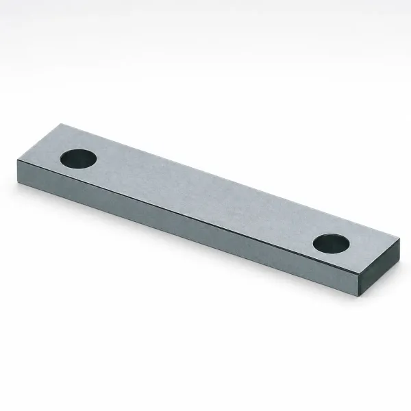
Venting depth runs 0.02 to 0.04 mm at flow ends and weld-line traps. Amorphous PEI flashes less readily than LCP, so the vents handle air, not flash. Trapped air burns at a 370 to 400°C melt and carbonizes at the weld. Keep vent land at 3 to 5 mm, then open the relief channel behind it. Vent each cavity, not just the parting line, because air traps appear wherever two cores meet.
Runners and gates must be generous for a viscous melt. Full-round runners of 6 to 10 mm on multi-cavity tools keep shear and pressure drop low. Edge gates at 50 to 80% of wall thickness with a 0.5 to 1.0 mm land fill most parts. Avoid sub-1.0 mm pin gates; they shear the melt and blush the surface at these temperatures.
Weld lines deserve the deepest respect here. Flow fronts that meet in an amorphous resin do not heal. There is no crystalline re-growth to recover strength, so the weld stays a weak plane. Position welds away from stress and cosmetic zones, vent them, and treat them as bonded joints in the design review.
Hot runners handle PEI well when built for it. Open-tip and valve-gate nozzles with 6 to 10 mm bores keep pressure low, and heater zones must hold 370 to 400°C. Dead pockets in the manifold become carbon traps, so spec a full-radius flow path. Slides and lifters need hot-clearance fits, because every component grows with the mold. Set those clearances at running temperature, not at the assembly bench.
Processing Window
Moisture control starts in the dryer. PEI absorbs humidity fast, so dry at 150°C for 4 to 5 hours with a -40°C dew point. Target exit moisture below 0.02%. Resin that sits hot for 8 hours in the hopper can yellow, so match hopper residence to the shot rate. A desiccant dryer with a sealed hopper is mandatory; hot-air dryers cannot reach 0.02%.
Melt temperature spans 340 to 425°C, with most grades run at 370 to 400°C. Below 360°C the melt is too stiff to pack thin sections. Above 410°C the residence time budget gets short. Keep shot residence under 6 to 10 minutes and purge dead spots to avoid carbon specks.
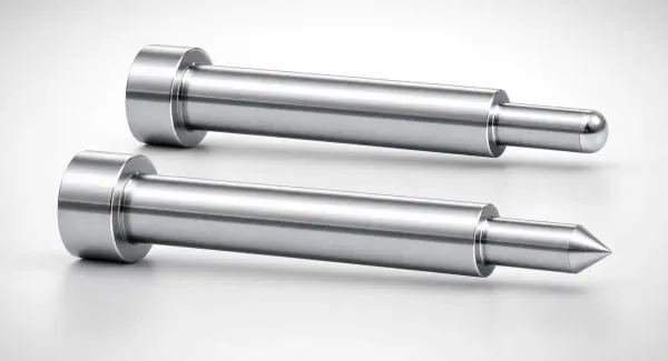
Injection pressure runs high, typically 100 to 150 MPa, and the machine must deliver it at the screw, not just on the gauge. Use a moderate, profiled fill speed, then a firm hold that packs the cavity before the gate freezes. Back pressure stays low at 0.3 to 1.0 MPa to limit shear heating of the melt.
Mold temperature holds at 120 to 180°C by zone. The last 20% of the cavity is where the set point matters most, so place the sensing thermocouple at the flow end. Cooling sets the cycle clock; parts eject near 150°C or below, still well above shop floor temperature. Uneven cooling warps amorphous parts, so zone control matters as much as total cycle time. Slope the set point a few degrees hotter at the gate end to keep the last cavity flowing.
The press matters as much as the mold. PEI needs a barrel rated to 420°C and a low-compression screw that does not over-shear the melt. Standard nitrided barrels wear quickly on glass grades, so spec bimetallic barrels for filled programs. Small shot volumes on big machines overstay residence time and carbonize, so match machine size to the shot.
Anneal where dimensional stability is critical. A post-mold soak at 150 to 170°C in air or oil relieves molded-in stress and stabilizes the part before inspection. Confirm the anneal cycle against the grade datasheet, since glass-filled grades respond differently from unfilled ones.
Plan the first trial like an experiment. Record cavity temperature in the last 20% of fill, injection pressure, and residence time for every shot. Let parts cool to 23°C and rest 48 hours before critical measurement. PEI parts that look good hot can still move 0.05 to 0.1% as they equilibrate.
Common PEI Applications: Medical, Aerospace and Electrical
Medical devices lead PEI tooling volume: steam-sterilizable instrument housings, surgical handles, and fluid-contact components. Reusable devices survive hundreds of autoclave cycles and resist disinfectants. The mold side demands polished cavities and thin, deep cores. Tooling details follow our medical core pin specification guide, with market context on our medical devices page.
Electrical and EV programs mold high-voltage connectors, busbar insulators, and battery components from PEI at V-0 wall thicknesses. The EV and energy industry page shows the connector tooling patterns these parts share.
Aircraft interiors pick PEI for low heat release and low smoke, and 20 to 30% glass grades replace metal brackets near engines. The mold runs exactly like the connector tool: hot cavity, hardened inserts, and vents at every flow end. All three sectors share one mold skeleton: heating zones, hardened inserts, and vents at 0.02 to 0.04 mm.
Defects: Mold-Side Root Causes
Short shots trace to flow resistance, not press settings. PEI's viscous melt freezes in thin sections when the gate is undersized, the runner is cold, or the cavity sits below 120°C. Check gate depth against wall thickness first, then confirm the last 20% of fill actually reaches 120 to 180°C.
Splay and surface bubbles point back to the dryer. Moisture above 0.02% hydrolyzes the melt and reads as silver streaks near the gate. Re-dry the lot and verify the dryer dew point before touching the mold.
Gate-area blush and halos come from shear, not heat. A pin gate under 1.0 mm or a sharp runner transition overheats the melt locally. Open the gate land, round the transition, and check melt temperature at the nozzle, not the barrel zone readout.
Weak weld lines are the amorphous signature defect. Flow fronts meet and do not recover strength, so a broken boss is usually a weld placed under load. Vent the weld zone, raise mold temperature, and move the weld off the stress path in the part design.
Black specks and burned streaks mean degradation somewhere in the melt path. Look for dead spots in the runner system, cold slugs caught at the gate, and residence times above 10 minutes at 400°C. On the mold side, polish runner transitions and open any sharp corner that traps material. Degraded resin also drops impact strength, so watch the part, not just the color.
Flash is uncommon but appears late on glass-filled programs. It usually signals parting-line wear, a soft cavity edge, or clamp tonnage that dropped as the mold grew hot. Check gate inserts and core edges for erosion, since glass fiber at 400°C melt is an abrasive slurry; inspect them every 50,000 to 100,000 shots.
Sticking and ejector marks come from thermal grip, not shrinkage grip. The part contracts four times faster than the steel core as both cool. Draft of 0.5 to 1.5° per side and a polished core surface are the real ejector aids. Warpage follows uneven cavity temperature, so zone-balance the heater circuits before blaming the resin.
Flow marks and faint blush are process prints of a cold tool. The skin freezes, hesitates, and re-melts as packing pressure pushes forward. Raise mold temperature toward 180°C on long-flow parts and accelerate fill through the hesitation zone. Sink is rare because amorphous PEI shrinks only 0.5 to 0.7%, so ribs at 50 to 80% of wall thickness rarely show. A hesitation mark at the same spot on every shot points to a mold-temperature valley, not the material.
PEI vs PEEK vs PSU: Choosing a High-Heat Amorphous Resin
Three resins compete for high-heat duty, and the choice changes the mold. PEI and PSU are amorphous; PEEK is semicrystalline. The table compares typical published values for the grades each program is most likely to quote.
| Property | PEI (Ultem) | PEEK | PSU |
|---|---|---|---|
| Structure | Amorphous | Semicrystalline | Amorphous |
| Glass transition (Tg) | ~217°C | ~143°C | ~185-190°C |
| Crystalline melting | None | ~343°C | None |
| HDT at 1.82 MPa | 200-210°C | ~152°C unfilled; ~315°C at 30% glass | ~174°C |
| Continuous service | ~170°C | ~250°C | ~150-160°C |
| Tensile strength, unfilled | 100-110 MPa | 90-100 MPa | ~70 MPa |
| Density | 1.27 g/cm³ | 1.30 g/cm³ | 1.24 g/cm³ |
| Mold shrinkage | 0.5-0.7% isotropic | 1.0-1.8% directional | 0.6-0.7% isotropic |
| Natural color | Amber, transparent | Beige, opaque | Light amber, transparent |
| Steam sterilization | Hundreds of cycles | Repeated cycles | Family claims 1,000+ cycles |
| Relative resin cost | Middle | Highest | Lowest of the three |
← swipe to scroll →
Table: typical published values for injection-molding grades; confirm against the specific supplier datasheet.
Price runs lowest for PSU, middle for PEI, and highest for PEEK, and each rung buys more temperature. PSU wins where extreme autoclave cycle counts or tight budget matter and service stays near 160°C. PEI beats PSU on strength and stiffness in the 150 to 200°C band, which is why it dominates thin-wall electrical parts. PSU parts also show better hydrolytic stability in hot water, so review the fluid spec before deciding.
PEEK takes over above 200°C continuous, in aggressive solvents, or where creep under load at temperature is the failure mode. The crystalline alternative fills a different mold: directional shrinkage near 1.0 to 1.8%, a hotter cavity, and its own steel rules. Those rules are detailed in our PEEK material guide.
Match the resin to the validation burden, not just the datasheet. Medical programs that document hundreds of autoclave cycles fit PEI, while PSU is the family that claims 1,000 plus. Where strength at temperature is the spec, compare retention curves at 150°C, not room-temperature tensile. The mold then follows the resin: PEEK needs directional compensation, while PEI and PSU compensate isotropically.
Watch solvents, not just heat. PEI resists acids but some solvents and halogenated hydrocarbons attack it. PEEK survives a wider chemical map, and PSU also needs solvent screening before reuse applications. Run the chemical compatibility check before the mold commit, because resin change orders after steel is cut are the expensive kind.
FAQ: PEI Injection Molding
Q1. Is Ultem the same thing as PEI?
Ultem is SABIC's trade name for its polyetherimide family. Generic PEI from other suppliers is chemically similar, but grades differ in fill level, viscosity, and datasheet values. Qualify supplier, grade, and datasheet when you quote a mold, not just the brand. Glass-filled grades differ in flow too, so request melt flow data with the mechanicals.
Q2. Why does PEI need a mold at 120 to 180°C?
Amorphous PEI freezes in internal stress when the skin cools below Tg during fill. A cold mold gives short shots, warpage, and poor dimensional stability. The hot mold keeps the melt mobile until packing finishes, then cools the part uniformly from about 150°C. Expect short-shot trials whenever the cavity reads below 120°C; heat the tool before tuning anything else.
Q3. Can PEI replace PEEK in my part?
Only if continuous service stays near 170°C and the chemical map fits. PEEK wins above 200°C, under broad solvent attack, and in long-term creep at temperature. If PEEK is overkill, PEI usually beats PSU on strength and stiffness in the 150 to 200°C band.
Q4. How many autoclave cycles does PEI survive?
Typical PEI parts tolerate hundreds of steam cycles, and each supplier publishes its own sterilization data. The 1,000-plus autoclave cycle claims belong to the PSU family, not PEI. Confirm cycle counts with the grade supplier before a reusable-device launch. Ask for the sterilization report; marketing claims hide grade-to-grade scatter.
Q5. What steel and vents does glass-filled PEI need?
Plan cavity steel at 48 to 52 HRC with gate inserts at 58 to 62 HRC for 20 to 30% glass grades. Cut vents 0.02 to 0.04 mm deep and keep gates generous for the viscous melt. Inspect gates and core edges every 50,000 to 100,000 shots for erosion. Gate wear shows first as rounded parting-line edges at the gate, so measure them at each mold audit.
The Bottom Line
PEI asks a mold for three things: a 120 to 180°C cavity, flow channels sized for a viscous melt, and steel that holds an edge. The payoff is V-0 parts with low isotropic shrink, uniform compensation, and continuous service near 170°C. The resin rewards tooling that treats 400°C melt and a 150°C steel mold as routine.
Do the property work before steel is cut. Compensate 0.5 to 0.7% uniformly, fit slides hot, and cut 0.02 to 0.04 mm vents. Harden gate inserts for glass grades, dry to below 0.02%, and keep residence short at 370 to 400°C. Document cavity temperature and pack pressure at first article so the next program starts from a known state.
DieStrike builds high-heat tooling under IATF 16949 with 120+ machines. Cavities run in hardened steel at HRC 62, with geometry at ±0.005 mm standard and ±0.002 mm precision. Molds ship in 2 to 5 weeks, and connector OEMs such as TE Connectivity, Amphenol, and Luxshare run high-temperature programs on them.
KEEP READING
Related Reading
Liquid Silicone Rubber (LSR) Injection Molding Guide
LSR is a two-component platinum-cured thermoset with a -50°C to +250°C service range and its own mold-side rules: hot molds, deliberate venting, and overflow…
Read articleArticle5 Shrinkage Compensation Rules for Mold Design
Shrinkage compensation decides mold accuracy. Five rules cover material rates from 0.3% to 2.0% and the cavity math that follows…
Read articleArticleInjection Mold Manufacturing Services
Precision injection molds for high-heat resin programs: 120+ machines, hardened cavity steel, and geometry held to ±0.005 mm standard…
Read articleArticleHow to Specify Core Pins for Medical Mold Tooling
Thin, deep medical features live and die at the core pin. Diameter, steel grade, hardness, and venting rules for small-diameter pins…
Read articleNEXT STEP
Ready to Start Your Mold?
Send us your element dimensions or part numbers — our team responds within 24 hours with pricing and lead time.

Written by
Ray ChanMold Buyer's Guide Author · Precision Mold Manufacturing Specialist. Ray helps global importers, distributors and OEMs source factory-direct molds and mold parts.