
How to Design Molds for Aerospace Parts: Tolerances and Traceability
Table of Contents
A PEEK bracket leaves the molder at 42.04 mm on a 42 mm bolt-hole span and arrives at the airframe plant at 42.11 mm. Both benches are calibrated. One drawing limit applies, and it is ±0.05 mm from a single datum scheme. The 0.07 mm gap came from a cavity cut to ±0.02 mm and a shrinkage value copied from a generic data sheet. No machine setting closes that gap once the steel is hard. Aerospace tooling punishes this twice, in scrap parts and in a first article report that cannot be signed.
The Snapshot
- Aerospace drawings commonly hold ±0.05 mm on critical features, so cavity dimensions must land inside 20-30% of that budget, or ±0.010-0.015 mm.
- DieStrike holds mold dimensions to ±0.005 mm and mold part geometry to ±0.002 mm, with cavity inserts heat treated to HRC 62.
- PEEK melts at 360-400 °C and runs in molds heated to 175-205 °C, which rules out any steel that softens above 200 °C.
- A 30% glass-filled grade wears an unhardened gate land 0.05-0.15 mm per 100,000 shots, and part dimensions move with the gate.
- Aerospace tools often run 5,000-25,000 shots over 10-15 years, so tool cost per part can exceed machine cost per part.
Why Aerospace Tolerances Start in the Mold
Aerospace drawings carry two tolerance classes at once. Bearing bores, seal grooves and connector keyways sit at ±0.05 mm or tighter. Secondary features such as mounting flanges and cable reliefs run at ±0.13-0.25 mm. A tool that holds the loose class and misses the tight one passes its own inspection and fails the customer's.
Molded aerospace parts are usually small, structural and low in volume. A typical program runs 500-20,000 parts per year across 10-15 years of platform life. That mix changes the design priority. Cycle time and cavitation count for little. Dimensional repeatability across a tool life measured in decades counts for almost everything.
Tool life at that scale is not shot count alone. A tool that sits idle for eight months between campaigns collects rust, hardened grease and slow dimension drift. Storage, re-qualification and re-documentation become real line items in the tooling budget.
DieStrike builds this class of tooling under IATF 16949 process control on 120+ machines, with DFM feedback returned inside 24 hours. Aerospace work also overlaps connector and electronics programs, and the same discipline runs through our connector and electronics tooling work.
How Part Tolerances Become Mold Tolerances
Start with the shrinkage data, not the drawing. A mold dimension is the part dimension adjusted for shrinkage, and the accuracy of that adjustment sets the ceiling on what the tool can hold. Data sheet values are single numbers. Real molded shrinkage varies by 0.2-0.6 percentage points across wall thickness, flow direction and gate location.
Directional shrinkage is the first trap. Unfilled PEEK shrinks 1.0-1.4% with modest anisotropy, while 30% glass-filled PEEK drops to 0.2-0.5% and can split 0.1-0.3 points between flow and cross-flow. Cut a rectangular bracket from the flow-direction value alone and the long side lands outside tolerance while the short side sits dead center.
Glass and carbon filled grades also shrink differently near a gate than at the far end of the flow path. A 120 mm flow length can carry a 0.05-0.12 mm difference in mold shrinkage effect between gate-adjacent and last-fill zones. Gate location is therefore a dimensional decision, not only a filling decision.

Then allocate the tolerance budget. A common industry practice gives the mold 20-30% of the part tolerance, keeps the process inside another 40-50%, and leaves the rest for measurement and material variation. That rule is worth applying feature by feature, because a single blanket cavity tolerance leaves tight features exposed.
Tolerance stack-up closes the loop. Stack the cavity dimension, shrinkage error, tool wear, machine repeatability and measurement uncertainty, and compare the total against the drawing limit. When the stack exceeds the limit, the fix is design or process, not tighter inspection.
| Part feature | Typical part tolerance | Mold cavity budget | Verification |
|---|---|---|---|
| Critical bore or boss diameter | ±0.05 mm | ±0.010-0.015 mm | CMM at 20 ±2 °C |
| Bolt-hole span over 100 mm | ±0.10 mm | ±0.020-0.030 mm | CMM with datum alignment |
| Thin rib wall thickness | ±0.08 mm | ±0.015-0.025 mm | CT scan or section cut |
| Seal groove depth | ±0.05 mm | ±0.010 mm | CMM touch probe |
| Flatness over a 50 mm face | 0.10 mm total | 0.020 mm total | CMM flatness scan |
← swipe to scroll →
Table note: part tolerances are typical aerospace figures for molded structural details. Mold cavity budgets follow the 20-30% allocation rule and assume a qualified shrinkage study.
Aerospace Resins and What They Do to the Tool
The resin decides the steel. Aerospace programs lean on high-temperature and filled grades because of heat resistance, flame requirements and stiffness per gram. Each family pushes the tool in a different direction, and the mold design has to answer all of them.
PEEK and PEI run hot. PEEK processes at 360-400 °C melt with a mold at 175-205 °C, and PEI runs 340-400 °C with a mold at 150-180 °C. At those mold temperatures the cavity insert is a heat source itself, so oil heating, insulated plates and thermal isolation between the cavity stack and the base become structural requirements.
PPS and PPA sit one step lower. PPS processes at 300-340 °C with a mold at 130-150 °C, and PPA at 300-330 °C with a mold at 120-140 °C. These grades are common in connector shells and brackets, where glass loading of 30-40% is normal. Corrosive by-products appear in some grades and push the cavity steel toward stainless.
Reinforcement is the wear driver. Glass fiber at 30% loading acts like a slow grinding wheel on gate lands, core pins and ejector edges. Carbon fiber adds thermal conductivity on top of abrasion, so the melt freezes faster against the cavity wall and needs shorter flow lengths or bigger gates. Both effects are covered in more depth in our guide to glass-filled resin tooling.
Unfilled PA and PA blends still appear in clamps, ducts and interior fittings. They run cooler, but they are hygroscopic and can release acidic residue during a long campaign. Detail rules for the hot end of this family are in our high-temperature resin tooling guide.
Steel Selection and Wear Compensation
Build gates and cores for the worn condition, not the new one. A gate land that wears 0.10 mm over 100,000 shots changes fill pressure, fill time and the shrinkage field around it. Part dimensions follow the gate even when the cavity itself is untouched.
Through-hardened H13 or 1.2343 at 46-52 HRC handles unfilled PEEK, PPS and PEI well, provided the tempering temperature sits above the mold operating temperature. A steel tempered at 200 °C that runs at 200 °C loses hardness slowly across thousands of hours. Powder metallurgy tool steels at 60-64 HRC carry the filled grades, and they hold a polished edge far longer on core pins and gate inserts.
Coatings buy life on sliding and flowing surfaces. PVD layers at 2-5 µm and 2,000-4,000 HV cut wear on gate lands and ejector edges without changing the base steel. Nitriding at 0.1-0.3 mm case depth gives a 60-63 HRC skin that keeps mold edges sharp. Neither treatment fixes a poor steel choice underneath.
Wear compensation is a design decision made before the first cut. Cut a new gate insert at the low end of the land length and plan the maintenance step that opens it later. Keep a spare cavity insert, a spare gate insert and a spare set of core pins in the tool package. For a low-volume tool, a spare insert written into the original order costs a fraction of an emergency rebuild.
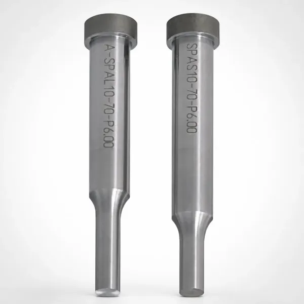
Know what each grade can and cannot take. The table below pairs the common aerospace resin families with a working steel choice, hardness range and the failure mode that drives the decision.
| Resin and loading | Cavity steel | Hardness | Design note |
|---|---|---|---|
| Unfilled PEEK, PEI, PPS | 1.2343 or 1.2344 (H11/H13) | 46-52 HRC | Temper above 250 °C for a 200 °C mold |
| 30% glass-filled PEEK or PPS | Powder metallurgy tool steel | 60-64 HRC | Gate land wears 0.05-0.15 mm per 100k shots |
| 30-40% carbon fiber PA or PPS | PM steel plus PVD coating | 60-64 HRC | Higher melt conductivity shortens flow length |
| Corrosive or acidic grades | S136 ESR stainless | 48-52 HRC | Pitting shows first in vents and shut-offs |
| Sharp-detail long-life insert | Nitrided H13 | 60-63 HRC case | Case depth 0.1-0.3 mm, re-nitride at rebuild |
← swipe to scroll →
Table note: hardness ranges are typical industry figures for mold-grade tool steels. Final selection depends on flow analysis, gate style and required tool life.
Hot Runner or Cold Runner for Aerospace Volumes
Volume decides this question, and aerospace volume is low. A program that turns 800-6,000 parts a year rarely justifies the cost and heat management of a hot runner system. A hot runner drop adds 6,000-15,000 USD per gate position, plus controls and a melt channel that must run 30-60 °C above the resin melt temperature.
Heat is the real barrier. A PEEK manifold at 420 °C grows about 1.5 mm per 300 mm of length compared with a cold tool, and every nozzle, seal and locating pin has to absorb that movement. Thermal isolation plates, expansion gaps and torque-controlled edge seals turn a straightforward tool into a precision assembly. Leaks at those temperatures damage insulation, wiring and the cavity in a single event.
Cold runners bring their own cost. On a 6 g aerospace bracket, a cold runner of 4-8 g means 40-55% scrap in every shot, and PEEK scrap sells for a fraction of virgin pellet price. Cold runners also freeze against a 200 °C mold differently than against a 60 °C mold, so the runner must be sized for a longer cooling path and often a larger full-round section.
Draw the line with three checks. Run a hot runner when annual volume exceeds 10,000 parts, when the part is under 2 g, or when the melt channel can be kept at a stable ±5 °C without extra heaters. Use a cold runner when the program is below 5,000 parts a year, when the grade is carbon-filled, or when the tool must sit idle for months at a time. The trade-offs are laid out in more depth in our comparison of hot runner and cold runner tooling.
If you do specify a hot runner, change three details. Use valve gates with hardened tips for any fiber-filled grade, since an open gate wears into an oval seat within 50,000-100,000 shots. Specify a manifold steel that keeps hardness at 450 °C, not a standard 1.2343 plate. And route every heater and thermocouple so it can be replaced without pulling the manifold out of the base.

Insulated runners split the difference and suit low volume well. A 3-6 mm melt channel machined into a plate that is isolated from the cooled base holds resin fluid for a few shots, then freezes clean into a removable runner slug. The tool stays simple, the scrap is recoverable and no heater fails at 03:00 before a qualification run.
Thin Walls, Ribs and Molded-In Inserts
Weight targets turn into thin walls, and thin walls turn into tooling rules. Structural aerospace details commonly run 0.8-1.5 mm nominal walls with a rib grid. At that thickness the mold is a set of long, slender cores, and stiffness, venting and ejection all get harder at once.
Keep rib base thickness at 0.5-0.6 times the wall and rib height at or under 3 times the wall for fiber-filled grades. Unfilled grades tolerate 2.5-3.5 times the wall. Above that ratio the core pin flexes under 800-1,200 bar of cavity pressure and the rib wanders off center by 0.05-0.15 mm.
Give every rib 1-2° of draft on each face and a 0.3-0.5 mm tip radius. Rounded tips release cleanly, while square tips drag glass fibers and leave scratch marks. Space ribs no more than 2.5 times their height apart, because that spacing is what keeps the core standing straight and lets air escape between ribs.
Watch the corners where walls meet. A sharp internal corner concentrates stress and creates a thicker section that cools last, so the part sinks or voids at exactly the point a fatigue crack will start. Run a 0.5-1.0 mm internal radius and keep the local section within 1.3 times the nominal wall.

Molded-in inserts carry the load path. Most aerospace brackets and housings bond a metal insert into a plastic body so a bolt can clamp to metal instead of resin. Boss outside diameter should run 1.5-2.0 times the insert diameter, which leaves a 1.5-3.0 mm wall around a typical M4 insert.
Hold the insert in the mold on a core pin with a 0.02-0.05 mm clearance, warm it to 60-120 °C before the shot, and check insertion force across the first 50 shots. A cold insert pulls heat out of the melt, and the resulting local shrinkage difference shows up later as a loose insert or a stress crack at the boss.
Reduce the risk with a knurl, a groove or a hex flat on the insert body. Relying on molded shrinkage alone to retain a smooth insert works until the tool wears and the boss grows 0.03 mm. At that point the insert rattles in the assembly and the whole lot is suspect.
Cooling and Mold Temperature for High-Melt Resins
A hot mold needs oil, not water. PEEK, PEI and PPS run in molds held at 130-205 °C, above the practical limit of a water circuit. Oil temperature controllers sized 6-12 kW per tool, rated to 250 °C, keep the cavity steady within ±3 °C, and that band is what holds shrinkage values stable across a run.
Channel placement changes with the target temperature. Standard rules put cooling lines 12-18 mm from the cavity surface, spaced 2.5-3.0 times the channel diameter. On a 1.0 mm thin wall with a hot mold, conformal cooling at 8-10 mm from the surface shortens cycle by 15-30% and evens out the temperature across a rib grid.
Isolate the cavity stack. Insulated plates, 3-5 mm air gaps and ceramic stand-offs stop 200 °C heat from soaking into the base and the platens. Without isolation, the machine spends energy heating the whole assembly and the leader pins grow enough to change alignment.
Cooling time follows wall thickness squared, so thin walls are not automatically fast. A 1.0 mm wall in PEEK needs roughly 8-12 s to reach a stable ejection temperature, a 2.0 mm wall needs 2.0-2.5 times that, and a 3.0 mm wall needs 4-5 times. Plan cycle at 30-60 s for a thin structural part on a hot tool, not the 15-20 s a production ABS tool would run.
Differential cooling controls warp. Running the moving half 5-10 °C hotter than the fixed half bends a warped bracket back toward flat, and it is a cheaper fix than rebuilding a cavity. Verify the setting with a first-shot dimensional report rather than by eye.
Ejection and Handling of Thin Aerospace Parts
High-temperature resins eject stiff and cool fast. Unfilled PEEK holds a modulus near 3.6 GPa at room temperature, so parts release with less sticking than a soft polyolefin but crack easily under a point load. Ejection design becomes a stress problem rather than a sticking problem.
Start with ejector pin clearance. In a 200 °C mold, pins grow 0.02-0.04 mm over a 100 mm length, so a cold-built 0.02 mm clearance can close at operating temperature. Machine clearance at 0.03-0.05 mm for the hot side, use nitrided or DLC-coated pins and pair them with self-lubricating bushings to avoid galling.
Size the ejection area for the resin, not the geometry. Stiff filled grades release at 10-20 MPa of projected area, which usually lands near 2-5% of clamp tonnage on a small tool. Spreading that force across more pins or a stripper plate keeps local stress under the 30-40 MPa a thin rib can take before it whitens.
Choose the mechanism by part shape. Thin-walled cups and rings eject cleanly from a stripper plate. Flat covers and panels use air poppets plus four to eight pins. Long thin brackets need a guided ejector plate so the pins stay parallel within 0.02 mm across the stroke.
Vent depth matters more on a hot tool. Keep vents at 0.015-0.025 mm deep with a 2-3 mm land and relieve to 0.5 mm behind it. The same depth in the parting line and at the last-fill corner prevents the 900-1,500 bar burn marks that appear when trapped gas cannot escape a fast-filling thin section.
Handle parts after ejection too. Thin aerospace details should be robot-picked or guided into a chute, never dropped, because a 0.9 mm rib that survives 25,000 cycles can still crack on a 300 mm fall. Every handling step belongs in the process sheet next to the tool.
Fits, Clearances and Surface Finish
Alignment hardware carries the precision of a hot tool. At 200 °C a 100 mm steel span grows 0.25-0.35 mm, so leader pins, bushings and side locks have to tolerate that movement or fight it. Guide bushings with 0.02-0.03 mm running clearance at room temperature sit near zero clearance at operating temperature, which is where alignment has to be correct.
Machining tolerance does not survive assembly by itself. A cavity insert held at ±0.005 mm in a pocket cut to ±0.02 mm lands wherever the pocket puts it. Cut the pocket, the insert seat and the shut-off surfaces as a matched set, and record those values in the tool report. This is the same discipline described in our guide to reading GD&T callouts as a mold buyer.
Surface finish is a functional call, not a cosmetic one. Structural aerospace parts usually sit at Ra 0.4-0.8 µm, seal grooves at Ra 0.2-0.4 µm and bond surfaces at Ra 1.6-3.2 µm from a controlled bead blast. A glossier cavity than the drawing needs costs 10-25% more in polishing hours and holds no benefit.
Shut-off and parting line quality set the flash limit. For PEEK and PPS, shut-off lands should be 3-8 mm wide and flat within 0.02 mm, with parting line flatness inside 0.03 mm over 300 mm. Above that the tool flashes at 900 bar, and flash on a heat-resistant part is difficult to remove without damaging the edge.
Finish also interacts with wear. A polished gate land at Ra 0.4 µm releases fiber-filled melt with less drag than an EDM finish at Ra 1.6 µm, and it wears more evenly. Budget a light polish after every 50,000-100,000 shots rather than a full rebuild.
Inspection and the Document Chain: FAI, AS9102 and CMM
In aerospace, an unverified dimension does not exist. The part has to be measured against the drawing, the tool has to be measured against its own report, and both sets of data have to survive the program. That chain is what separates aerospace tooling from general industrial work.
First article inspection follows AS9102. The standard defines three forms, and the mold shop and molder feed all three. Form 1 covers part number, drawing revision and the signature block. Form 2 lists every drawing characteristic with its tolerance, measured result and pass or fail status. Form 3 records the material and process certifications behind the part.
A full FAI requires a ballooned drawing, where every dimension, note and specification is numbered on the print. A molded aerospace detail can carry 60-250 ballooned characteristics. The layout report then measures each one on a CMM, a vision system or hand tooling rated for the tolerance.

CMM work needs controlled conditions. Measurement runs at 20 ±2 °C, with machine specification stated as MPE values under ISO 10360-2, and with a test uncertainty ratio of at least 4:1 against the tolerance being checked. A ±0.05 mm characteristic measured with a 0.02 mm uncertainty instrument produces a number nobody can defend.
Document the tool, not just the parts. Keep a mold dimensional report from first cut, steel certificates with heat numbers, a heat treatment record showing HRC 62 at the cavity, coating thickness reports and a cavity identification stamp on every insert. Add a maintenance log that records each teardown, measurement and repair with date and shot count.
Traceability reaches down to cavity level. If cavity 3 runs 0.04 mm high on a seal groove, the log must show which parts came from cavity 3, over what date range, and at what shot count the drift started. Without that link, a dimensional escape becomes a full-lot recall instead of a targeted containment.
Quality system expectations sit with the tier suppliers in the chain. AS9100 registration is the usual requirement for aerospace suppliers, and special processes such as heat treatment, plating and non-destructive testing are commonly routed to NADCAP-accredited shops. DieStrike works to IATF 16949 process control, provides full dimensional and material documentation with every tool and routes special processes through qualified partners.
Low-Volume Tooling: TCO and Lead Time
A low-volume aerospace tool is a capital asset, not a consumable. A single-cavity PEEK bracket tool typically runs 15,000-45,000 USD, and a multi-feature housing with side actions can reach 60,000 USD. Split across 5,000-25,000 lifetime parts, the tool alone carries 1.50-6.00 USD per part.
That number is where quotes should be compared. Take two quotes for the same bracket, one at 22,000 USD and one at 28,000 USD. If the cheaper tool needs a cavity rebuild at 40,000 shots and the other does not, the cheaper quote costs more by the end of the program.
Cost levers that actually move a low-volume tool:
- Cavitation. A single cavity costs 25-40% less than a two-cavity tool and suits 500-5,000 parts a year.
- Runner type. Cold runners avoid 6,000-15,000 USD per hot runner drop and remove the heater control package.
- Steel grade. H13 at 48-52 HRC covers unfilled grades and saves 15-30% against powder metallurgy inserts.
- Side actions. Each slide or lifter adds 1,500-4,500 USD, so a redesign that removes an undercut is worth real money.
- Spares. A spare gate insert and core pin set adds 3-6% and removes the risk of a multi-week rebuild.
Lead time follows the same logic. DieStrike builds injection molds in 2-5 weeks, and standard components such as ejector pins, core pins, sprue bushings and mold bases ship in 3-7 days. Add 1-2 weeks for hot runner manifolds and PVD or nitriding queues, then 2-4 weeks for trial shots and first article approval before production release.
Ongoing cost is easy to ignore and hard to recover. Storage in a controlled, dry environment, re-qualification after a long idle period, dimensional re-verification at every campaign start and documentation updates all land in the TCO. A tool that is properly preserved and logged costs 2-5% of its price per year to hold in a ready state.
DieStrike runs this class of work under IATF 16949 process control with 120+ machines, holds mold dimensions to ±0.005 mm and mold part geometry to ±0.002 mm, and returns DFM feedback within 24 hours. The same tooling discipline serves connector OEMs including TE Connectivity, Amphenol and Luxshare, where small features and tight gauges are routine.
FAQ: Aerospace Mold Design
Q1. What tolerance should I specify on an aerospace mold?
Give the mold 20-30% of the part tolerance on critical features. For a ±0.05 mm bore that means ±0.010-0.015 mm on the cavity, verified with a dimensional report at 20 ±2 °C. Looser features at ±0.25 mm can take a ±0.05 mm cavity budget without risk.
Q2. Can I run glass-filled PEEK in a standard H13 tool?
H13 at 48-52 HRC survives unfilled PEEK but not 30% glass fiber at volume. Gate lands and core pin edges wear 0.05-0.15 mm per 100,000 shots. Use powder metallurgy steel at 60-64 HRC for gates and small cores, and keep H13 for the base and plates.
Q3. Do aerospace molds need a hot runner?
Rarely below 10,000 parts a year. A hot runner drop costs 6,000-15,000 USD and needs a 420-450 °C manifold with expansion management. Cold runners with a well-sized full-round channel handle 500-5,000 parts a year at lower risk, at the cost of 40-55% runner scrap on small parts.
Q4. What documentation should ship with the tool?
Mold dimensional report, steel certificates with heat numbers, heat treatment records, coating reports, cavity identification stamps and a maintenance log. Part data follows AS9102 with Forms 1, 2 and 3, plus CMM layout results at a 4:1 test uncertainty ratio.
Q5. Why does an aerospace mold cost more than an ABS tool?
Harder steels, hot-oil mold temperature control, thermal isolation, tighter shut-offs, spares and documentation. Expect a 30-60% premium over a general-purpose production tool of the same size. Over 10-15 years and 25,000 parts, that premium works out to a few cents to a few dollars per part.
Before release, run one last check on the drawing. Confirm every tolerance band has a matching cavity budget, every cavity has an identification stamp, and the FAI plan names the instrument for each characteristic. That review costs two hours and prevents the version of this problem that ships.
The Bottom Line
Aerospace parts live or die on the mold tolerance, not the press. Give the cavity 20-30% of the part tolerance, choose steel that keeps hardness at 200 °C, design gates and cores for the worn condition, and document every dimension to AS9102. A low-volume tool that holds ±0.005 mm is cheaper than a rebuild.
Send your drawing and material callout through the contact form and our team will return a tooling review within 24 hours.
KEEP READING
Related Reading
How to Read a CMM Report: Dimensional Data for Mold Buyers
Datums, MPE, probing strategy and the 4:1 test uncertainty rule that decides whether a measured value counts.
Read articleArticlePEEK Injection Molding: High-Temp Material Guide
Melt windows of 360-400 °C, mold temperatures of 175-205 °C and shrinkage values that drive PEEK tooling dimensions.
Read articleArticleHow to Run a Mold Trial: T0, T1, T2 and First Article Approval
A staged trial sequence that turns a new tool into signed dimensional data before the first article file is closed.
Read articleServiceMold Design & DFM
Mold flow analysis, tolerance stack-up review and steel selection for tight-tolerance programs, with 24-hour feedback.
Read articleNEXT STEP
Ready to Start Your Mold?
Send us your element dimensions or part numbers — our team responds within 24 hours with pricing and lead time.

Written by
Ray ChanMold Buyer's Guide Author · Precision Mold Manufacturing Specialist. Ray helps global importers, distributors and OEMs source factory-direct molds and mold parts.