
How to Design Molds for Cleanroom Molding: Particles and Corrosion
Table of Contents
An ISO Class 7 line can stop on one ejector pin that ran dry for 4,000 cycles. The cavity still holds ±0.005 mm, the cycle still hits 22 s, and every part passes dimensional checks. Then the in-line counter reads 400,000 particles ≥0.5 µm per m³ at the mold opening, and the run is dead. Cleanroom molding punishes the tool, not the machine.
The Snapshot
- ISO 14644-1 Class 7 allows 352,000 particles ≥0.5 µm per m³, while Class 8 allows 3,520,000. The mold decides which limit the line can hold.
- Oil-free tooling uses graphite-bronze or PTFE-lined bushings, bonded dry films at 5-15 µm, and no grease anywhere in the cavity stack.
- Corrosion-resistant cavity steels sit at S136 48-52 HRC, 420 stainless 50-54 HRC and 17-4PH 40-44 HRC, all typical industry figures.
- Coatings that survive daily cleaning include electroless nickel at 12-25 µm and 500-700 HV, plus DLC at 2-5 µm and 2,000-4,000 HV.
- A cleanroom-ready tool typically costs 15-30% more than a standard medical mold and adds 1-2 weeks to a 2-5 week build.
Why Cleanroom Molding Changes Mold Design
A cleanroom is an air-management system wrapped around a molding machine. ISO 8 rooms typically run 20-60 air changes per hour, and ISO 7 rooms run 60-150. The mold sits inside that envelope, often under a laminar flow hood at 0.45 m/s ±20%. Every gram of grease and every worn sliding fit adds to the particle load the filters must remove.
The tool becomes a source, not just a part holder. A general-purpose mold sheds wear debris from 20-40 sliding interfaces. That debris stays local and gets wiped up at the end of a shift. In a cleanroom that debris lands on the cavity and transfers to the part. It then shows up in a particle count 2-3 stations downstream.
Cycle economics change as well. Medical parts often run 20-40 s cycles on 50-200 tonne presses, and a tool may complete 5,000-20,000 shots per campaign. Maintenance windows are short because every room entry needs gowning plus a 30-60 minute cleaning cycle. Design decisions must cut the maintenance frequency, not only the cycle time.
DieStrike builds this class of tooling for medical device programs and other regulated work. The wider device supply chain is covered on our medical devices industry page.
ISO 14644 Class 7 and 8: What the Mold Must Deliver
ISO 14644-1 sets the particle limits that decide your mold architecture. Class 8 permits 3,520,000 particles ≥0.5 µm per m³. Class 7 permits 352,000, a limit roughly 10 times tighter. That single order of magnitude changes lubrication, sealing and vent design at the same time.
Most medical molding runs in Class 8 with a Class 7 zone around the mold opening. High-risk work, such as implant-adjacent parts or sterile barrier components, may push the whole tool zone to Class 7 or better. Table 1 lists the limits and what each one forces on the tool.
| ISO 14644-1 class | ≥0.5 µm limit per m³ | ≥5 µm limit per m³ | Mold-side requirement |
|---|---|---|---|
| Class 5 | 3,520 | 29 | Fully sealed tooling zone, no exposed sliding fits, wipe-down every 2,000-5,000 shots |
| Class 7 | 352,000 | 2,930 | Oil-free bearings, wiper seals on slides, vents at 0.01-0.015 mm |
| Class 8 | 3,520,000 | 29,300 | Dry-running fits, bonded dry film, controlled vents and drain paths |
← swipe to scroll →
Table note: particle limits are typical ISO 14644-1 values for the stated classes. Requirement column is mold design practice, not a standard callout.
Two numbers matter for tooling more than the headline count. The ≥5 µm fraction drives visible contamination on optical and implant parts. The mold opening area also sees the highest particle concentration of any point in the room. A filter cannot help once debris leaves the parting line 300 mm from a finished part.
Particle Generation Points in a Mold
Map the tool by contact pressure and relative motion. Fits that move under load produce the most debris per cycle, while fits that only align under light load produce far less. Rank every interface into those two groups before the design is released.
- Ejector pins and sleeves. A 0.02-0.04 mm radial clearance puts two metal surfaces in motion for 20-100 mm per cycle. Dry steel on steel galls after roughly 5,000-50,000 cycles and then sheds hard particles.
- Cam slides and lifters. A 15-25 degree cam angle converts 30-80 mm of mold opening into 8-30 mm of lateral travel. Wear plates slide under full side load.
- Leader pins and bushings. Four guides carry a 400-1,200 kg mold half through every close at 10-30 cycles per minute.
- Hot runner contacts. Manifold growth of 1-2 mm at 200-300 °C slides steel on steel under spring preload.
- Return and gas springs. Coil springs rub their bores, and coated rods can wear 0.01-0.05 mm per 100,000 strokes.
Secondary sources matter too. Plated hardware can flake, and zinc or cadmium coatings are barred in most device plants for shedding reasons. Brass and copper alloys wear quickly and should stay out of the cavity stack. Stainless hardware at A2 or A4 grade is the safer default.
Design intent. Replace sliding steel contact with a dry-running bearing material wherever load allows it. Keep hard, smooth, corrosion-resistant surfaces only where alignment better than 0.01 mm is mandatory.
Oil-Free Lubrication Design
Grease is the fastest route to a failed particle count. One finger of lithium grease in a bushing can release 10-50 mg of oil mist over 100,000 cycles. That mist condenses on cold cavity surfaces and traps airborne particles. Remove grease from the design and you remove the trap.
Self-lubricating bushings. Graphite-filled bronze guides carry 10-25% graphite by volume and run with no added lubricant. PTFE-lined steel bushings hold a 0.02-0.05 mm liner and keep friction coefficients near 0.05-0.15. Both handle the 5-20 MPa contact pressure of a leader pin under 30-80 kN of closing force.

Dry film lubricants. Where a bearing is impossible, apply a bonded MoS2 or PTFE dry film at 5-15 µm. Renew it at each 50,000-100,000 shot service. Dry films do not migrate, so they cannot reach the cavity.
Hard coatings. DLC at 2-5 µm and 2,000-4,000 HV drops the friction coefficient to 0.1-0.2 on ejector pins and slides. Electroless nickel with PTFE co-deposition runs 12-25 µm thick at 500-700 HV after heat treatment. Both cut friction and wear debris at the same time.
Avoid oil-based mold releases, oil mist lubricators and volatile hydraulic fluids. Where hydraulics are unavoidable, specify a sealed circuit with a low-volatility fluid and route every line outside the laminar zone. A cleanroom tool has no oil cup to refill, and that has to be designed in rather than maintained out.
Corrosion-Resistant Steels and Coatings
Cleanroom cleaning is aggressive by tooling standards. A tool may see alkaline cleaner at pH 9-11, 70% IPA wipes, autoclave steam at 121-134 °C or vaporized hydrogen peroxide at 30-35% concentration. A plain P20 cavity at 30 HRC will pit under that routine within 12-24 months.
Steel choice is a corrosion decision first. S136 ESR (1.2083) carries about 13.6% chromium and holds 48-52 HRC, so it resists both pitting and wear. AISI 420 stainless at 50-54 HRC suits inserts and slides. 440C at 56-58 HRC covers core pins under 3 mm diameter where stiffness matters more than toughness. All values are typical industry figures.
Watch the chlorine line. Free chlorine above 20-50 ppm in a cleaning bath attacks 420 stainless at grain boundaries and starts pits that grow into crack initiation sites. Specify citric acid passivation per ASTM A967 after any polishing or EDM work on stainless cavities.
| Material or coating | Hardness (typical) | Corrosion resistance | Cleanroom use |
|---|---|---|---|
| S136 ESR (1.2083) | 48-52 HRC | High | Cavity and core, transparent and medical parts |
| AISI 420 stainless | 50-54 HRC | Moderate to high | Inserts, slides, wear plates |
| 440C stainless | 56-58 HRC | Moderate to high | Core pins and sleeves under 3 mm |
| Electroless nickel (Ni-P) | 500-700 HV at 12-25 µm | High | Ejector pins, slides, water fittings |
| DLC coating | 2,000-4,000 HV at 2-5 µm | High | Pins, gates, lifters, high-wear fits |
← swipe to scroll →
Table note: hardness, thickness and corrosion ratings are typical industry figures. Final selection depends on resin chemistry, cleaning agents and sterilization method.
Nitriding still earns its place here, but with a caveat. A 0.1-0.3 mm gas-nitrided case at 900-1,100 HV improves wear and adds mild corrosion resistance. The white layer must be removed afterwards because it is brittle and can spall into the cavity. Salt bath nitriding is a poor fit for stainless parts that must stay bright.

DieStrike machines these corrosion-resistant grades with the same ±0.002 mm component geometry used on all regulated work. Steel selection for the broader medical case is compared in our guide to mold steel for medical-grade molds.
Venting and Particle Control
Vents do two jobs in a cleanroom tool. They release trapped gas, and they decide how much resin can flash onto a surface that staff must then clean. Tighten too far and you buy short shots plus burn marks, so the numbers have to sit inside a narrow band.
Vent depth. A cleanroom tool typically runs 0.01-0.015 mm deep vents, against 0.02-0.03 mm on a general-purpose mold. Polypropylene tolerates 0.02 mm before flashing, and polycarbonate flashes near 0.015 mm. The cleanroom value sits below both limits on purpose.
Vent land and relief. Keep the land 2-3 mm long, then relieve to 0.5-1.0 mm to atmosphere. A long land at 0.01 mm is hard to clean and blocks after 5,000-10,000 shots. Short lands with generous relief vents clean out with a 0.3 mm brass shim in under a minute.
Route every vent to a channel that drains away from the cavity, not across the sealing face. Vents that dump gas 50-100 mm from the part put wear debris directly into the laminar stream above the molding. Add a vacuum-assist circuit at 300-600 mbar where the part has thin ribs or 0.5-1.0 mm walls. Vacuum also cuts burn marks and short shots without adding vent depth.
Avoid porous sintered vent inserts in this application. Resin and cleaner residue plug them after a few thousand shots, and they cannot be restored by wiping. A machined vent plus periodic shim cleaning is the more serviceable choice.
Ejection and Moving Component Rules
Ejection is where most cleanroom particle events start. The fix is not better grease. The fix is a design that removes lubricant from the stroke path and keeps debris moving away from the part.
Pin fits and materials. Hold 0.02-0.04 mm radial clearance on ejector pins. Specify nitrided, DLC-coated or bronze-plated pins for any pin under 2 mm diameter. Coat the bore as well where the plate is steel. That combination survives 500,000-1,000,000 strokes without grease.
Guided ejection. Add 2-4 ejector plate guide pillars with self-lubricating bushings. Unguided plates cock by 0.05-0.2 mm and scrape the pin bores on every stroke. Bronze-plated guide bushings cost a few dollars more and remove that wear path.
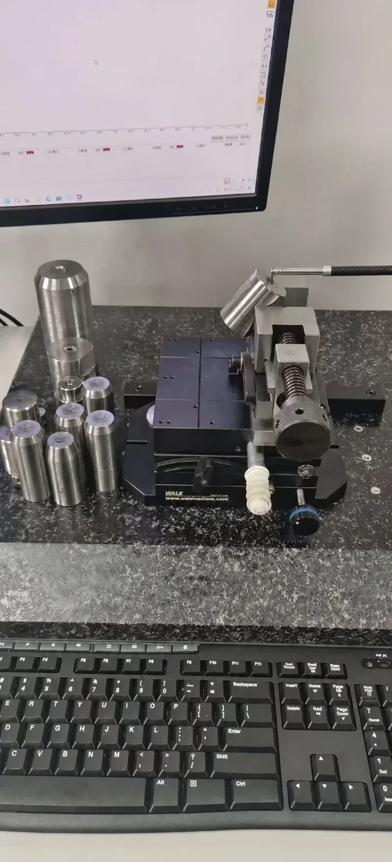
Slides and lifters. Seal cam slides with PTFE wipers and spring-return them so they park away from the cavity. Keep the slide body behind the mold plate line where the room air sweeps past it. Never expose a lubricated wear plate within 150 mm of the cavity. Where a design allows it, replace a slide with a collapsible core or an unscrewing unit on sealed bearings.
Keep spares on the shelf. Standard components such as ejector pins, sleeves and bushings ship in 3-7 days. A planned change-out then fits inside one room entry instead of two. DieStrike holds these items as standard stock for regulated programs.
Surface Finish and Cleaning Access
A surface that is easy to wipe beats a surface that is merely smooth. Cleaning staff work through gloves with lint-free wipes, so every pocket, undercut and blind hole has to be reachable in one pass.
Finish targets. Hold cavity roughness at Ra 0.2-0.4 µm, which lands near SPI A2 to B1. Polish along the direction of ejection so residue slides off instead of catching. A Ra 0.8 µm cavity that holds resin residue will need cleaning 2-3 times more often than a Ra 0.3 µm cavity.
Geometry for cleaning. Radius every internal corner at 0.5 mm minimum. Sharp corners hold resin crumbs and cleaner residue. Keep blind holes shallower than 5 times their diameter, or add a drain path to the outside. Water-line plugs should seal with an O-ring or bonded seal, never with pipe dope that can migrate into the room.
Cooling circuits. Target 2-3 m/s water velocity and Reynolds numbers above 10,000 for turbulent flow. Filter the supply at 25-50 µm and eliminate dead legs where biofilm grows. Biofilm on a stainless circuit releases particles and endotoxin onto parts. Stainless manifolds, brazed fittings and a closed loop with a return filter keep the circuit clean between services.
Group all service points on one side of the mold where possible. Air, water, sensor and hot runner connections on one manifold face cut the time staff spend reaching over the cavity with tools.
Cleanroom Mold Maintenance and Cleaning
Maintenance in a cleanroom is expensive because access costs 30-60 minutes of gowning and room recovery. The schedule should be built around shot counts, not calendar weeks.
- Every 5,000-10,000 shots. Wipe the cavity, parting line and vent lands with 70% IPA and lint-free wipes. Check vents with a shim. Look for resin crumbs near ejector pins.
- Every 50,000-100,000 shots. Pull the tool, inspect coatings, measure pin clearances with pin gauges, and renew bonded dry film on slides and plates.
- Every 12-24 months. Re-plate worn nickel surfaces, re-polish cavities to Ra 0.3 µm, and replace all bushings showing more than 0.02 mm of wear.
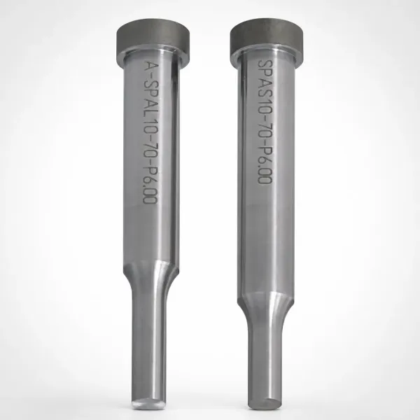
Accept or replace thresholds. Replace an ejector pin once clearance exceeds 0.06 mm. Re-coat any surface that has lost more than 50% of its coating thickness. A DLC layer down to 1 µm still works, but a 0.5 µm layer is a wear source.
Storage between campaigns. Store in a dry cabinet below 40% relative humidity, or in a VCI bag with a corrosion inhibitor. Stainless steels still pit in a humid room over 6-12 months. Tag every tool with its last service date, shot count and coating status.
Verify cleaning with data. Run 20-30 dry cycles after a wipe-down and sample the air at the mold opening. A reading under 50% of the room limit gives you margin for a full production run. DieStrike documents these service events so the record travels with the tool.
How Cleanroom Mold Design Feeds IQ, OQ and PQ
Validation data is easier to defend when the tool design already answers the questions a reviewer will ask. Design decisions made 8-12 weeks before the first trial determine how many documents you must produce later.
IQ, installation qualification. The mold arrives with steel certificates to EN 10204 3.1 and plating reports at 12-25 µm. A dimensional report covers ±0.005 mm on critical mold dimensions. Cleaning agent compatibility statements for every surface finish belong here too.
OQ, operational qualification. Run the tool for at least 30 minutes of continuous production and across 3 consecutive lots. Sample particle counts at the start, middle and end of each lot at the mold opening. A cleanroom tool that drifts upward by more than 50% across a 3-hour run has a wear or lubrication problem, not a room problem.
PQ, performance qualification. Capability usually needs Cpk ≥1.33 for general device work, and many medical programs set 1.67 on critical dimensions. Cavity-to-cavity variation under 0.02 mm keeps a 4-cavity tool inside those limits without frequent adjustment.

Document the mold itself, not just the process. A change log covering pin replacement, coating renewal and cavity re-polish gives the reviewer a traceable history. DieStrike supplies that record with the tool, and our walkthrough of IQ, OQ and PQ for medical tooling covers the file structure in detail.
Cost and Lead Time Impact
Cleanroom-ready tooling costs more. The premium is typically 15-30% over an otherwise identical medical mold, and it lands in specific line items rather than in a vague surcharge.
- Steel and coatings. S136 ESR or 420 stainless instead of P20 adds 10-25% to the cavity stack, and DLC or nickel plating adds a further 5-15%.
- Bearing hardware. Self-lubricating bushings, guide pillars and coated pins add 3-8% to the component bill.
- Sealing and venting. Wiper seals, vacuum-assist circuits and tighter vent EDM work add 5-10%.
- Documentation. Material certificates, plating reports and dimensional layouts add 2-5%.
Lead time grows by 1-2 weeks on a 2-5 week injection mold build. Most of that sits in coating and plating queues at 3-7 days per process, plus a longer finish and cleaning sequence. Book plating capacity with the steel order rather than after machining.
Reduce cost without cutting cleanliness. Buy standard bushings, pins and springs rather than custom ones. Metal 3D printed or cast inserts rarely pay off against stainless at these volumes. Get a design review before steel is cut, so tolerances stay tight where they matter and open where they do not. DieStrike returns DFM feedback within 24 hours and works to IATF 16949 process control on 120+ machines.
FAQ: Cleanroom Mold Design
Q1. Do cleanroom molds need stainless steel cavities?
Not always, but stainless is the default for Class 7 work. S136 at 48-52 HRC or 420 stainless at 50-54 HRC resists the pH 9-11 cleaners and IPA wipes used between campaigns. A P20 cavity at 30 HRC will pit within 12-24 months under the same routine, and pits become particle traps.
Q2. Can I still use grease on leader pins in a cleanroom?
No. Grease releases 10-50 mg of oil mist per 100,000 cycles and the mist condenses on the cavity. Use graphite-bronze or PTFE-lined bushings, or a bonded dry film at 5-15 µm renewed every 50,000-100,000 shots. Both keep friction low without airborne oil.
Q3. What vent depth works for cleanroom molding?
Run 0.01-0.015 mm deep with a 2-3 mm land, then relieve to 0.5-1.0 mm. That is roughly half the 0.02-0.03 mm used on general-purpose tools, and it stays under the flash limit of polycarbonate near 0.015 mm. Add vacuum assist at 300-600 mbar instead of deepening the vents.
Q4. How often should a cleanroom mold be cleaned?
Wipe down every 5,000-10,000 shots with 70% IPA and lint-free wipes. Pull and inspect the tool every 50,000-100,000 shots, then re-plate and re-polish on a 12-24 month cycle. Each room entry costs 30-60 minutes of gowning and recovery, so batch the work.
Q5. How much more does cleanroom tooling cost and take?
Expect a 15-30% cost premium and 1-2 extra weeks on a 2-5 week build. The money goes into corrosion-resistant steel, coatings, self-lubricating hardware, sealed slides and documentation. Skipping it usually costs more in failed particle counts and unplanned teardowns.

One more check before release. Confirm that every lubricated surface sits at least 150 mm from the cavity and outside the laminar path over the part. If any does not, redesign it now rather than during a failed run.
The Bottom Line
Cleanroom molds fail on particles, not on dimensions. Choose corrosion-resistant steel, remove grease from every fit, keep vents at 0.01-0.015 mm and clean on shot count. Budget 15-30% more and 1-2 weeks longer for a tool that holds ISO 14644 Class 7 or 8.
Send your part data to our team through the contact form and we will return DFM feedback on the tool architecture.
KEEP READING
Related Reading
Injection Mold Validation: IQ, OQ, PQ for Medical Tooling
How mold documentation, runs and capability data move a cleanroom tool through IQ, OQ and PQ with Cpk targets attached.
Read articleArticleHow to Specify Core Pins for Medical Mold Tooling
Diameter, clearance and coating choices that keep small medical core pins accurate and free of corrosion pits.
Read articleArticleNitriding vs PVD Coatings for Mold Steel: Which Surface Treatment When
Case depth, hardness and cost compared for 0.1-0.3 mm nitrided cases against 2-5 µm PVD layers.
Read articleServiceMold Repair and Maintenance
Teardown, re-plating, fit recovery and documentation for regulated tools returned to production.
Read articleNEXT STEP
Ready to Start Your Mold?
Send us your element dimensions or part numbers — our team responds within 24 hours with pricing and lead time.

Written by
Ray ChanMold Buyer's Guide Author · Precision Mold Manufacturing Specialist. Ray helps global importers, distributors and OEMs source factory-direct molds and mold parts.