
How to Design Rotary Index Molds: Multi-Station Insert Tooling
Table of Contents
A four station rotary index tool for overmolded connector contacts reached trial with 0.06 mm of runout across the index joint. The cavities measured correct to print, and the joint still pushed a 0.15 mm fin on every station after the first index. Grinding the plate face and re-cutting the face cam cost a 6 week schedule slip and a rebuild of the shut-off land. This guide sets out the numbers that prevent that: index accuracy, plate architecture, drive choice, melt feed, joint clearance and wear life.
The rules below assume a thermoplastic rotary index mold with 2 to 8 stations, whether the plate sits in the fixed half or the moving half.
The Snapshot
- Index accuracy of 0.01 to 0.02 mm. Face cams and a precision spindle set plate position at every step. Runout above 0.02 mm shows up as a step between stations and a fin at the joint.
- A cycle 20 to 40 percent shorter than a fixed-plate insert tool. Station 1 loads while station 2 molds and station 3 discharges, so handling time leaves the cycle.
- Shut-off lands at 0.02 to 0.05 mm, vents at 0.01 to 0.02 mm. Those two numbers on the sliding face decide whether the index joint seals or flashes.
- Payback starts above 5 to 10 million parts. A four station rotary mold runs 40 to 100 percent over a fixed-plate equivalent, and the index plate itself is a consumable.
What a Rotary Index Mold Is: Plate, Stations and Spindle
A rotary index mold carries its cavities on a plate that turns inside one half of the tool. The plate is a two-part assembly: a fixed ring bolted to the mold base, and a rotating disk carried on a precision spindle at the center. The disk steps through 360 degrees divided by the station count, then clamps and molds like a fixed tool.
Station counts run 2 to 8. A four station plate indexes at 90 degrees per step and a six station plate at 60 degrees. Each station holds a segmented insert, a hardened pocket that carries the insert body on one face and the overmold cavity on the other. The same pocket takes a bare insert at load, cavity steel in the middle of the cycle, and a finished part at discharge.

Index accuracy separates a working tool from a flashing one. Face cams and the spindle hold the disk to 0.01 to 0.02 mm in axial and angular position at every step. DieStrike holds ±0.005 mm on mold geometry overall, with ±0.002 mm on EDM and jig grinding work, and that capability level is what makes the cam and spindle fits repeat over millions of cycles.
The plate can sit in the fixed half or the moving half. Fixed-half rotation shortens the melt path because the drop tubes barely move. Moving-half rotation lets gravity assist part discharge on a vertical machine. Both layouts run in production, and the melt feed architecture usually decides which one a program takes.
Treat the index joint as a functional surface, not an assembly convenience. Every section below flows from that single idea, because the joint carries the same melt pressure as a parting line while also sliding.
When Rotary Beats a Fixed Insert Tool
The gain from a rotary plate is time overlap. A fixed-plate insert mold stops the press for the moment a robot or operator places the next insert set. A rotary tool loads station 1 while station 2 molds, station 3 overmolds, and station 4 discharges. Handling time leaves the critical path, and the cycle drops 20 to 40 percent against an equivalent fixed-plate tool.
The arithmetic is predictable. A 30 second fixed-plate cycle with 6 seconds of insert load and 3 seconds of discharge becomes a 20 to 24 second rotary cycle in most programs. On one tool that lifts output from 120 shots an hour to 150 or 171 shots an hour, which is the difference between needing three tools and needing two.
Rotary tooling also stabilizes where the insert lands. A hand-loaded pocket repeats within 0.1 mm on a good shift. A machined pocket on an indexed plate repeats at 0.02 to 0.05 mm, because the pocket sets the position and the operator does not.

Typical programs fit the pattern: two-shot seals molded onto a carrier, electrical contacts overmolded with insulation, and button assemblies with a soft cap over a hard body. Contact insert work for tier-1 programs at TE, Amphenol, Luxshare and Dongshan follows the same shape, with a placed terminal body and an overmolded housing. The overmolding guide covers bond chemistry and shrinkage matching, which is a separate decision from plate architecture.
Two limits kill the idea early. A part larger than about 200 mm across forces a plate too heavy to index stiffly, and a program under 5 million pieces rarely repays the tool premium. Run the payback math before a drawing set is released.
Index Plate Design: Segmented Inserts, Face Cams and Runout
The plate is a ground steel disk on a forged carrier, with a hardened sliding face at the joint and pockets for the station inserts. Segmented inserts let one station come out without dismantling the tool. A damaged cavity then leaves the plate in 30 to 60 minutes instead of a full teardown, which matters on a tool that runs three shifts.
The sliding face carries the mechanical load. Specify it at HRC 58 to 62, ground and lapped, with flatness within 0.01 mm across the joint diameter. Softer faces peen at the shut-off land, and the clearance opens on its own inside the first 200,000 to 500,000 cycles. DieStrike heat treats cavity and joint steel to HRC 62 maximum and finishes the cam and spindle fits to ±0.002 mm.
Face cams do two jobs at once: they index the disk and they clamp it. A V-face cam pulls the disk into the ring and locks it at each station, so the mold closes on a locked plate instead of a floating one. Clamp load should resist 10 to 20 percent of the injection force. Below that, the plate shifts under fill pressure and prints a step on the part.

Runout rules belong on the drawing: plate face runout within 0.01 mm, pocket to pocket location within 0.02 mm, spindle radial clearance within 0.005 mm. Thermal growth is the hidden term in all three. A 400 mm plate at 120 °C grows roughly 0.45 mm across its diameter, so the spindle fit, cam preload and ring clearance are set cold to allow for that expansion.
Standard components such as leader pins, sprue bushings and fasteners ship in 3 to 7 days from the main suppliers, which keeps a rebuild on schedule. The plate is a custom part, and it sits on the critical path of the whole tool build.
Drive Selection: Servo, Hydraulic Rotary and Geneva
Three drive families index a mold plate, and each fits a different control requirement. An external servo drive couples through the mold base to the spindle, usually with a planetary gearbox and a shaft entering the fixed half. It gives the widest control over acceleration, dwell and index position.
A hydraulic rotary cylinder mounts inside the mold base and delivers high torque in a compact envelope. It suits large plates and heavy station inserts where an electric drive would need a large gearbox. The cost is oil at temperature near the tool and shaft seals that run at 80 to 120 °C.
A Geneva mechanism turns 60 to 180 degree steps with no controller at all. The pin and slot geometry fixes the step size, and the cam profile sets the dwell, so timing is built into the part. It is the most robust option and the least flexible one.
| Drive | Index time per step | Where it fits | Watch out for |
|---|---|---|---|
| External servo through the mold base | 0.3 to 1.0 second | Programmable dwell, 4 to 8 stations, mixed part families | Brake and torque limit needed at end of travel |
| Hydraulic rotary cylinder | 0.5 to 1.5 second | Large plates, heavy stations, high clamp load | Oil lines at 80 to 120 °C, seal wear at the base |
| Geneva mechanism | 1.0 to 2.0 second | Fixed step of 60 to 180 degrees, minimal controls | Step geometry locked at design, shock at the pin |
| Rack and pinion with a cylinder | 1.0 to 2.5 second | Retrofit plates, low station counts of 2 to 3 | Backlash at the rack, needs an external stop |
← swipe to scroll →
Table note: index times are typical values for a plate of 250 to 500 mm diameter at the stated torque. Confirm against the drive supplier curve and the plate inertia calculated for the real insert set.
Match index time to the machine, not to the fastest catalog figure. A 0.3 second index shortens the cycle but needs an end-of-travel brake and a torque limit to survive the shock. A 2 second index adds a full second of dead time to every shot, which on a 21 second cycle is a 5 percent output loss before the plate has molded anything.
Feeding Melt to a Rotating Plate
Melt has to cross a moving interface, and that interface is the highest-risk subsystem on a rotary tool. Two architectures exist: flexible drop tubes from a fixed manifold, or a slip-ring manifold that rotates with the plate.
Flexible tubes are the default choice. Braided stainless hose at 6 to 10 mm bore carries melt from a fixed hot runner manifold to each station drop. Routing matters more than the hose itself. Keep a bend radius of at least ten times the bore, keep the tube working in one plane, and never let a tube rub a plate edge. A tube routed that way runs 2 to 5 million cycles.

A slip-ring manifold seals melt between a rotating face and a static face. It saves space and shortens the melt path, and it adds a sliding seal that sees full melt pressure and 200 to 300 °C. Leak paths at that face reach the plate and the machine table, and a repair means pulling the manifold off the plate in the press.
A rotary union handles water and oil, not melt. Coolant and hydraulic lines cross the joint through a union with a sealed spigot, and the same union often carries the thermocouple bundle. The service rule is simple: log union torque and run a leak check every 50,000 cycles, and keep one spare drop tube per station on the shelf.
Put a thermal cutout on every drop and route thermocouples with the tubes. A tube that loses heat freezes melt in the bore, and the shot stalls before the plate has indexed. Standard hot runner components ship in 3 to 7 days, which is faster than most plate repairs, so spares are cheap insurance.
Sealing the Index Joint Against Flash
The index joint is a sliding parting line, and thermoplastic melt at 50 to 150 MPa looks for it on every shot. The seal is a steel-to-steel land, 4 to 8 mm wide, lapped and hardened, held at 0.02 to 0.05 mm clearance while the plate is clamped.
Vent the joint at 0.01 to 0.02 mm over a 2 to 4 mm land, then relieve to atmosphere. Anything deeper turns into a flash channel as the face wears. A 0.03 mm vent passes gas at low pressure and seals against melt at fill pressure in a correctly clamped tool.
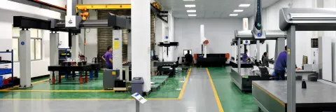
Hardness on the sliding face decides how long those numbers survive. A face and ring at HRC 58 to 62, ground and lapped to Ra 0.1 to 0.2 µm, holds its seal past 1 million cycles. A soft face at HRC 30 smears at the land, and the clearance can open inside a single week of production.
Diagnose flash by fin thickness. A 0.05 mm fin points to roughly 0.02 mm of joint clearance and a clamp problem. A 0.15 mm fin points to a land that never closed, usually from cam preload set too light or a plate that is not flat. A fin on one station only points to runout rather than clearance, and the fix is the plate, not the clamp.
Keep high-pressure melt away from the sliding face. Gates should not point straight at the joint, and thick sections belong near the plate center where clamp stiffness is highest. That single layout decision removes more flash risk than any change to the clearance number.
Wear, Maintenance and the Regrind Decision
The index plate is a consumable, and the tool file should say so on page one. Expected life before the first regrind runs 2 to 5 million cycles, depending on clamped area, melt pressure and how dry the joint runs. A spare plate ordered with the tool costs far less than a plate replacement in the middle of a program.
Measure the joint on a schedule, not on a symptom. A feeler check at the land plus a runout check on the plate face every 250,000 to 500,000 cycles shows which side has worn. Most programs set an administrative limit at 0.08 mm of land clearance, because past that the fin grows with every shot.
Leave 0.3 to 0.5 mm of grind stock on the plate face, enough for two regrinds before the pockets lose depth and the segmented inserts lose their seat. A new plate is a custom part and follows the same 2 to 5 week lead time as a tool build, so the spare belongs in the original order.
Daily habits extend plate life: grease the spindle and the cam track during run-in, keep resin dust off the joint face, and record shot count against each wear reading. Once the reading and the shot count sit on the same line, the next regrind can be scheduled into a planned shutdown instead of a crash stop.
Interlocks, Machine Signals and Cycle Control
Rotation is permitted only on a full mold-open signal. The interlock reads the machine mold-open output or a platen proximity switch, and it blocks the index cycle when that signal is missing. A plate that turns against closed steel destroys cavities and the spindle in one motion.
Build the chain as two channels. A single sensor that fails in the open state will let the plate rotate into a closed tool, and that failure mode justifies two switches and a monitored relay.
The sequence runs: mold open, ejector retracted, index enable, plate turn, brake, clamp confirm, mold close. Clamp confirmation comes from the cam lock signal rather than the drive position, because an encoder can report a correct angle while the cam has not seated.
Log the index count beside the shot counter in the tool file. Control drawings on an IATF 16949 program list the interlock function, the fail-safe state and the brake behavior on a power loss, and the mold trial verifies each item before the tool releases to production.
Cost Band and Payback Math
A four station rotary mold runs 40 to 100 percent over a fixed-plate equivalent. The premium sits in four places: the index plate and its grinding, the spindle and cam set, the drive and its controls, and the melt feed through flexible tubes or a rotating interface.
Put numbers on it. A fixed-plate insert tool quoted at 120,000 USD becomes a rotary tool at 168,000 to 240,000 USD. That premium comes back as machine hours and as labor removed from the cell.
A 30 second fixed cycle against a 21 second rotary cycle saves 9 seconds per shot. At 1 million parts that is 2,500 machine hours, worth about 62,500 USD at 25 USD an hour. At 5 million parts it is 12,500 hours, or 312,500 USD.
| Program volume | Fixed plate at 30 s | Rotary at 21 s | Hours saved | Value at 25 USD per hour |
|---|---|---|---|---|
| 1 million parts | 8,333 hours | 5,833 hours | 2,500 hours | 62,500 USD |
| 5 million parts | 41,667 hours | 29,167 hours | 12,500 hours | 312,500 USD |
| 10 million parts | 83,333 hours | 58,333 hours | 25,000 hours | 625,000 USD |
← swipe to scroll →
Table note: hours assume a single tool running the stated cycle with no downtime, and the dollar figure uses a 25 USD machine hour rate. Recalculate with the shop rate, the real cycle and the planned annual volume.
Below 5 million parts the savings sit inside the premium, and a fixed-plate tool with a robot loader is the lower-risk purchase. Above 10 million parts the rotary mold usually pays for itself inside the first program year. A mold manufacturing partner can quote both architectures from the same part data and let the volume decide.
Rotary vs Carousel vs Two Molds With a Robot
Rotary is one of three ways to overlap insert handling with molding. A carousel carries two complete mold faces on a rotating frame, so one face molds while the other loads. Two separate molds with a robot between them keep each tool standard and move the handling logic into the cell. A two-shot tool reaches a similar result by rotating between two injection units, and the two-shot mold guide covers that route.
The rotary plate keeps one clamp unit, one melt system and one set of process settings, which is what holds part quality steady across stations. The carousel duplicates every cavity and doubles the moving mass on the platen. Robot transfer between two molds uses proven hardware and two ordinary tools, and it adds a transfer step that can drop or misplace a part.
| Option | Capital vs fixed plate | Cycle effect | Main quality risk | Best fit |
|---|---|---|---|---|
| Rotary index plate in one mold half | Plus 40 to 100 percent | 20 to 40 percent shorter | Joint flash and plate runout | 5 to 10 million parts and above |
| Carousel with two mold faces | Plus 80 to 150 percent | 10 to 25 percent shorter | Two cavity sets must match | Large parts, 2 to 4 stations |
| Two molds with robot transfer | Plus 60 to 120 percent for two tools | 5 to 15 percent shorter | Transfer damage and placement | Mixed volumes, separate materials |
| Fixed plate with manual load | Baseline | Set by handling time | Insert placed to 0.1 mm or worse | Under 5 million parts |
← swipe to scroll →
Table note: capital bands compare a single-cavity-set fixed-plate tool against the stated architecture for the same part, and they exclude automation in the cell. Confirm against real quotes before the tool order.
Rotary Index Mold FAQ
Q1. What is a rotary index mold?
A mold that carries its cavities on a plate inside one half of the tool. The plate turns through 2 to 8 stations, so inserts load at one station while another molds and a third discharges. The overlap cuts the cycle 20 to 40 percent against a fixed-plate insert tool.
Q2. How accurate is the indexing?
0.01 to 0.02 mm from a face cam and a precision spindle. Those fits are ground and EDM cut to ±0.002 mm, inside the ±0.005 mm mold tolerance the shop holds on the rest of the tool. Runout above 0.02 mm shows as a step between stations.
Q3. When does a rotary mold pay back?
Above 5 to 10 million parts in most programs. The tool costs 40 to 100 percent more than a fixed-plate equivalent, and the return comes as machine hours. At 1 million parts a 9 second cycle saving is worth about 62,500 USD at 25 USD an hour.
Q4. How long does an index plate last?
2 to 5 million cycles before the first regrind, depending on clamped area and melt pressure. Leave 0.3 to 0.5 mm of grind stock for two regrinds, and measure the joint land every 250,000 to 500,000 cycles.
Q5. What causes flash at the index joint?
Joint clearance above 0.05 mm, cam preload set too light, or plate runout. Seal the land at 0.02 to 0.05 mm, vent at 0.01 to 0.02 mm, and keep the sliding face at HRC 58 to 62. A fin on one station alone points to runout rather than clearance.
The Bottom Line
A rotary index mold succeeds on four numbers: 0.01 to 0.02 mm of index accuracy, 0.02 to 0.05 mm of joint clearance, 0.01 to 0.02 mm of vent depth, and a volume above 5 to 10 million parts. Hold the first three and the plate repeats station to station for millions of cycles. Miss them and no process setting recovers the tool.
DieStrike builds rotary index and precision injection molds to IATF 16949 with ±0.005 mm mold accuracy, ±0.002 mm on EDM and jig grinding, cavity heat treatment to HRC 62 maximum, 120+ machines and DFM feedback in 24 hours. Tool lead times run 2 to 5 weeks, with standard components shipping in 3 to 7 days.
KEEP READING
Related Reading
How to Design Insert Molds: Retention, Loading and Cycle
Pocket clearance, insert retention and load-station geometry for tools that mold around a placed metal or plastic body.
Read articleArticleThe DFM Checklist: 20 Questions Before a Mold Is Cut
The review items that catch drafting, wall, tolerance and ejection problems before steel is committed.
Read articleArticleHow to Hold 0.002 mm Mold Tolerances
Grinding, EDM and inspection practice behind the tolerance stack on interchangeable mold components.
Read articleServiceInjection Mold Manufacturing
IATF 16949 mold building with DFM feedback in 24 hours, ±0.005 mm mold accuracy and 2 to 5 week lead times.
Read articleNEXT STEP
Ready to Start Your Mold?
Send us your element dimensions or part numbers — our team responds within 24 hours with pricing and lead time.

Written by
Ray ChanMold Buyer's Guide Author · Precision Mold Manufacturing Specialist. Ray helps global importers, distributors and OEMs source factory-direct molds and mold parts.