
How to Design Trim Dies for Die Casting: Degating and Flatness
Table of Contents
A trim press tool built to nominal casting geometry meets a robot cell that adds four seconds of dwell. The castings arrive at 38 °C instead of 95 °C, so the knife strips the runner root instead of shearing it. Eleven percent of one 4,000 piece shift goes back to the melt, and the tool plate has grown 0.12 mm across the shave station. The scrap and the rework put the launch twelve days behind plan. This article covers the second-operation trim tool: its cooling window, pierce-shave-coin layout, shear force, edge steel, locating datum and robot hand-off.
A380 aluminium at 130 to 170 MPa is the reference material. The flash runs 2 to 6 mm and the runner 20 to 60 mm on a 60 to 200 t trim press.
The Snapshot
- A 1 to 3 second trim window. The runner and the flash come off while the casting sits at 60 to 120 °C. Below 60 °C an A380 runner root cracks instead of shearing.
- 130 to 170 MPa shear at room temperature. A 500 mm runner perimeter cut 4 mm thick needs about 300 kN, plus 15 to 25 percent for the shave station and 40 to 60 percent of press rating for coining.
- Pierce, shave, then coin. The sequence holds flatness at 0.2 to 0.5 mm on a 150 mm casting and trim burr under 0.1 mm on a visible edge.
- D2 or SKD11 at HRC 58 to 62. Re-sharpen the trim edge every 20,000 to 50,000 castings, or burr height and knife-mark depth both double.
Why a Trim Die Is a Second-Operation Tool
The casting die sets the gates, the runner and the cooling layout, and it releases a part that still carries all three. Every die casting leaves the machine with a 20 to 60 mm runner, overflow wells and a 2 to 6 mm flash line. The trim tool is the second-operation press tool that removes the runner, the biscuit, the overflows and the flash.
A380 fills a die at 650 to 700 °C and ejects at 200 to 350 °C. A 3 mm wall then sheds 8 to 12 °C per second in still air. That rate creates the trim window, and it also closes it. Reach the knife at 60 to 120 °C and the runner shears clean. Arrive at 35 °C and the same cut cracks the root.

Shear strength decides the tonnage. A380 shears at 130 to 170 MPa at room temperature. At 60 to 120 °C that value falls to roughly 60 to 70 percent of it. A cold casting at 35 °C therefore needs 40 to 60 percent more knife force than the same casting at 95 °C.
The failure mode changes with temperature as well as with force. Shear sends stress into a 0.1 to 0.3 mm band behind the edge, and the root parts cleanly. A bending knife spreads the same load across the whole 1.5 to 3 mm root throat, and cast aluminium in tension tears along the grain.
That is why the trim tool and the robot hand-off have to be designed as one system rather than two purchases. The runner geometry that the trim knife has to cut is set inside the casting die, so both tools share a datum. The gate and runner geometry itself belongs to the article on designing die casting gates and runners.
The Trim Sequence and the Hand-Off Window
The extraction sequence runs against a clock. The casting die ejects at 200 to 350 °C. A robot gripper takes the part in 2 to 5 s, drops the runner to scrap and places the casting on the trim nest. A clamp closes, the knife strokes, and an ejector pushes the trimmed part to a deburr station.
Add the steps and the window is tight. Gripping takes 2 to 5 s, transfer 1 to 2 s, placement 0.5 to 1 s and clamping 0.5 to 1 s. The casting therefore reaches the knife 4 to 9 s after ejection. A 3 mm wall loses 8 to 12 °C per second. An 8 s hand-off costs 65 to 95 °C of the 300 °C ejection heat.
That leaves 60 to 120 °C at the knife, which is the ductile band for A380. Three cell changes recover a missed window. Shorten the gripper path to take 2 s off the transfer, or hold the casting in a heated nest at 80 to 100 °C. A third option is a trim station inside the machine cycle, where the part never cools below 130 °C.

The coining station sits last, so it runs cooler by design. Feed it at 60 to 90 °C and aluminium coins well at 2 to 4 percent strain.
Cooling on the casting die and the temperature the part arrives at are one decision viewed from two ends. Die insert temperature comes from the circuits described in the article on die casting die cooling design. The trim window is a consequence of that number, not a separate choice.
Tool Layout: Pierce, Shave, Coin
A trim die does three jobs and the order matters. The first station pierces the runner and the biscuit away from the part. The second shaves the flash line flush. The third coins the casting flat. Put the coin station first and the pierced runner drags across the coin pocket.
Piercing first removes 40 to 70 percent of the cutting tonnage in one clean stroke. The runner and biscuit hang off the part with no support behind them, so a shave knife would bend them over instead of shearing them. A straight pierce knife runs with 0.05 to 0.10 mm of clearance per side against a hardened die button. The scrap slug then falls free instead of hanging on the knife.
The shave station takes the flash line and any witness left at the parting line. Flash on a die casting runs 2 to 6 mm wide and 0.3 to 1.5 mm thick. It also sits on a line that moves 0.10 to 0.30 mm from shot to shot as the die blocks warm. A shave knife therefore needs a locating nest that holds the casting on a machined datum, not on the flash itself.
The coin or restrike station sets flatness. A 150 mm die cast housing often leaves the die with 0.8 to 1.5 mm of warp. The coin station brings that to 0.2 to 0.5 mm across the full face. Coining force runs 40 to 60 percent of the press rating, applied through a pocket machined to 0.03 to 0.05 mm flatness.

Fit the three stations into one die when the casting is under 250 mm and the press stroke allows it. Above that, or where a 100 mm transfer stroke is needed, split the work across two dies on the same press.
| Station | Function | Tool element | Share of load | Failure if wrong |
|---|---|---|---|---|
| 1. Pierce | Cut the runner, biscuit and overflows clear of the part | Straight knife, 0.05 to 0.10 mm per side against a die button | 40 to 70 percent of cutting load | A shave knife bends the unsupported runner and tears the root |
| 2. Shave | Take the 2 to 6 mm flash line flush with the part wall | Replaceable shave knife on a locating nest with a clamp pad | 15 to 25 percent of cutting load | Flash lifts the casting off the nest and the knife digs in |
| 3. Coin | Set flatness and press out the parting-line witness | Coin pocket insert machined to 0.03 to 0.05 mm flatness | 40 to 60 percent of press rating | Casting above 130 °C smears, below 60 °C cracks |
← swipe to scroll →
Table note: order and load shares are typical values for a 150 mm A380 housing on a 60 to 200 t trim press. Confirm the split on the actual casting.
Shear Force and Press Sizing
Size the press from the cut, not from the part weight. Shear force equals shear perimeter times thickness times the shear strength of the alloy.
Take the 500 mm runner perimeter of a mid-size housing. Cut 4 mm thick at 150 MPa and the pierce station needs 300 kN, which is 31 tonnes-force. Add 15 to 25 percent for the shave station and the cutting load lands at 34 to 39 tonnes-force.
Then add the coin station. Coining force runs 40 to 60 percent of the press rating. A 100 t press spends 40 to 60 t on the coin pocket alone.
Shear angle decides the shock load more than the steady load does. A flat knife on 4 mm aluminium peaks at 1.5 to 2.5 times the average force in a few milliseconds. Grinding a 3 to 5 degree shear angle across the trim punch spreads the cut over a longer stroke. It cuts the shock peak by 30 to 50 percent.
A 60 to 100 t press suits the 150 mm housing example with headroom for the coin stroke. Move to a 200 t press when the runner perimeter climbs past 900 mm, or when one stroke trims two castings.
DieStrike holds trim die plates to ±0.005 mm, with EDM and jig grinding at ±0.002 mm on the shave pockets. The tonnage arithmetic for this class of press tool follows the method in the article on calculating press tonnage for stamping dies.
Tool Steel, Coatings and Edge Life
Aluminium is the reason a trim edge wears out. At 100 °C and 20 to 60 MPa of contact pressure, aluminium transfers to bare tool steel. It builds a welded layer on the knife face. The edge then cuts through its own build-up instead of the casting, and the trim burr grows.
D2 or SKD11 hardened to HRC 58 to 62 is the default for aluminium trim edges. That band sits at the top of the DieStrike heat treatment envelope, which stops at HRC 62. Below HRC 56 the edge rolls at the shave station and the flash line burr doubles within 10,000 castings.
A coating takes the adhesion problem off the steel. TiAlN at 2 to 4 micrometres cuts the friction coefficient against aluminium from 0.4 to 0.6 on bare steel to 0.15 to 0.25. DLC at 1 to 3 micrometres works on the lightest trim knives, where the coating cannot chip under shock.

Make the flash-line knife replaceable, because the shave station wears fastest. A bolted insert returns the tool to production in 30 to 60 minutes instead of 8 to 16 hours of weld repair. It costs 20 to 40 percent of the die.
| Edge material | Hardness or build | Where it belongs | Watch-out |
|---|---|---|---|
| D2 or SKD11, bare | HRC 58 to 62 | Pierce knives on runners and biscuits | Aluminium transfer at 100 °C builds on the face |
| D2 with TiAlN | 2 to 4 micrometres on HRC 60 | Shave knife at the flash line | Re-coat after each regrind, because grinding removes the layer |
| D2 with DLC | 1 to 3 micrometres on HRC 60 | Light trim knives and coin pocket edges | Chips on impact, so never on a shock-loaded knife |
| SKD61 insert body | HRC 44 to 48 | Nest pads and clamp jaws | Too soft for a cutting edge, tough under repeated clamping |
← swipe to scroll →
Table note: grades, hardness bands and coating builds are typical industry values for aluminium trim tooling. Keep the heat treatment certificate and the coating thickness report in the tool file, and re-sharpen every 20,000 to 50,000 castings.
Put the regrind interval, the coating renewal and the insert replacement in the tool file. The interval structure in the article on planning die casting die maintenance runs on the same trigger-by-shot-count logic.
Locating the Casting Without Rocking
Locate the casting on a machined datum, never on a raw cast surface. A casting die face or an ejector boss machined flat to 0.05 mm gives the nest a stable plane. An as-cast wall carries 0.5 to 1.5 degrees of draft and 0.10 to 0.30 mm of position variation. A nest built against it lets the part rock.
Use a 3-2-1 fixture. Three pads take the primary plane, two pads stop rotation on a second datum and one pad sets the third. Pad faces of 8 to 15 mm diameter with a 0.5 to 1.5 mm land spread the clamp load without marking the casting.
Clamp before the knife moves. A hold-down pad at 2 to 8 kN presses the casting onto all three primary pads and holds it there for the whole stroke. The clamp closes 0.5 to 1 s before the knife and releases 0.5 s after it retracts. The part therefore never sits free between stations.
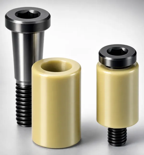
If the part lifts 0.05 mm off a pad, the shave knife sees a 0.05 mm step. Its clearance is only 0.05 to 0.10 mm per side. Burr height then doubles and the knife-mark depth moves from 0.02 to 0.15 mm. A CMM check on 30 castings at tryout catches the mode early.
Heat, Distortion and Tool Flatness
A trim press that runs castings at 90 °C does not stay at 22 °C. A 1.2 kg casting cooling 40 K releases about 43 kJ into the die, which is 7 kW of heat at 600 strokes per hour.
Steel expands 11 to 12 micrometres per metre per kelvin. A 200 mm tool plate that warms 25 K grows 0.055 to 0.060 mm across its length. That single number already exceeds the 0.05 mm flatness the tool needs.
Two controls hold the plate. The first is a cooling plate bolted under the shave and coin stations. It runs at 20 to 25 °C with 8 to 12 mm channels at 4 to 8 L/min. The second is a 1.5 to 3 s dwell between the shave and coin strokes.
Check plate flatness on a surface plate with a 0.02 mm indicator after warm-up, not cold. A 0.05 mm feeler gauge must not pass under any pad while the press sits at running temperature.
The Burr and Flatness Budget
The print usually controls two numbers on a trimmed casting. Burr on a visible edge belongs under 0.1 mm, and flatness on a 150 mm housing belongs at 0.2 to 0.5 mm. Both drift with edge wear and with tool heat.
Burr height tracks edge condition. A knife with a 0.02 mm edge radius shears with a 0.05 mm burr. Let the radius grow to 0.10 mm and the same cut leaves 0.15 to 0.25 mm, above the limit. That is why the interval is a shot count: re-sharpen every 20,000 to 50,000 castings.

Measure flatness the way a customer will accept it. Sit the casting on a surface plate and sweep the face with a 0.05 mm feeler. For a reported number, use a CMM with 5 to 9 points per face. A closed coin station holds 0.2 to 0.5 mm on 150 mm, which is 0.13 to 0.33 percent of the diagonal.
Deburr after trim rather than inside the tool. A 0.1 mm burr on a 500 mm perimeter is 50 mm of edge to blend. Log burr height on a 30 piece sample every shift, with the shot count of the last regrind beside it.
The Robot Interface and Hand-Off Repeatability
Placement accuracy decides whether the knife cuts aluminium or the nest. A robot that places a casting within 0.3 mm puts the flash line inside the shave clearance. A robot that drifts to 0.5 mm pushes the knife into the nest face and marks the casting 0.10 to 0.15 mm deep.
A 1.2 kg casting needs 35 to 50 N of holding force, which is three to four times its own weight. Vacuum cups of 20 to 40 mm suit flat faces, and mechanical fingers suit a casting with a flange to grip.
Cycle time has to fit the window. Gripping takes 2 s, transfer 1.5 s, placement 1 s and clamping 0.5 s. The stroke adds 0.5 s, so the cycle totals 5.5 s inside the 6 to 9 s band. Sensor the interface: a part-present switch at the nest and a clamp pressure switch stop the press before a knife hits an empty nest.
Cost: Hand Degating vs Trim Press vs In-Line Cell
Three routes remove a runner, and the labour math separates them. Hand degating runs a band saw and a deburr bench with 2 to 4 operators per shift. One trim press with a single tool runs one operator at 600 to 1,200 castings per hour. An in-line cell takes a quarter to half of one operator's time.
Put numbers on the shift. Three operators across 8 hours is 24 labour hours against 8 hours for one press and 4 hours for a cell. At a fully loaded 15 to 30 USD per hour, that is 240 to 480 USD per shift on the labour line alone.
| Route | Labour per shift | Output | Main cost driver | Main risk |
|---|---|---|---|---|
| Hand degating, band saw and deburr bench | 2 to 4 operators | 4,000 to 8,000 castings | Labour hours and saw blades | 3 to 8 percent root cracks from a cut at 30 to 50 °C |
| One trim press, single tool | 1 operator | 600 to 1,200 castings per hour | 60 to 200 t press plus one die | Changeover of 6 to 12 minutes per part number |
| In-line trim cell with robot | 0.25 to 0.5 operator | Matched to the casting machine | Robot, gripper, die and fencing | Placement drift above 0.3 mm knife-marks the part |
← swipe to scroll →
Table note: labour bands and output rates are typical values for a 150 mm A380 housing. Price the route against your own loaded labour rate.
Hand degating also hides a quality cost. Manual handling pushes the cut to 30 to 90 s. The casting reaches the saw at 30 to 50 °C, and the root cracks on 3 to 8 percent of parts.
DieStrike builds the casting die and the trim station that follows it. Work is held to IATF 16949 with 120+ machines and ±0.005 mm die tolerance, with tier-1 references including TE, Amphenol, Luxshare and Dongshan. Die lead times run 2 to 5 weeks, and standard components ship in 3 to 7 days. The die casting mold service page covers the die side of the same program.
Trim Die Design FAQ
Q1. How fast must the casting reach the trim die?
One to three seconds after ejection, at 60 to 120 °C. A 3 mm wall loses 8 to 12 °C per second in still air. A 9 s hand-off can drop the casting below the ductile band, and a cold root cracks instead of shearing.
Q2. How much force does a trim die need?
A380 shears at 130 to 170 MPa. A 500 mm runner perimeter cut 4 mm thick is 300 kN, about 31 tonnes-force. Add 15 to 25 percent for the shave station and 40 to 60 percent of press rating for coining.
Q3. Which steel belongs on a trim edge?
D2 or SKD11 at HRC 58 to 62, with a TiAlN layer of 2 to 4 micrometres on the shave knife. Re-sharpen every 20,000 to 50,000 castings, and re-coat because grinding removes the layer.
Q4. Why does the trim tool knife-mark the casting?
Locating is the usual cause. Locate on a machined die face or an ejector boss with a 3-2-1 pad set. Clamp at 2 to 8 kN before the stroke and hold robot placement inside 0.3 mm. A 0.05 mm lift against a 0.05 to 0.10 mm shave clearance doubles the burr.
Q5. Why does the flash line tear instead of shearing?
The casting is too cold for the alloy. Below 60 °C an A380 root goes into tension and tears along the grain. Trim inside 1 to 3 s at 60 to 120 °C. Alternatively fit a heated nest at 80 to 100 °C so the part holds the ductile band.
The Bottom Line
Four numbers decide whether a trim tool works. Trim the casting at 60 to 120 °C, within 1 to 3 s of ejection. Size the pierce station from 130 to 170 MPa of A380 shear, then add 15 to 25 percent for the shave. Hold the coin station at 40 to 60 percent of press rating. Keep the datum on 3-2-1 pads with a 2 to 8 kN clamp, and re-sharpen the edge every 20,000 to 50,000 castings.
The tool and the robot are one system, and the cooling window is the constraint that binds them. A cell that holds the hand-off under 9 s keeps every casting in the ductile band. A cell that adds dwell needs a heated nest, an in-line station, or a trim back inside the die. Every one of those choices is cheaper than a 3 to 8 percent crack rate at the runner root.
KEEP READING
Related Reading
How to Select Mold Steel for Die Casting Dies
Heat checking, thermal fatigue and the hardness bands that survive 100,000 shots of 650 °C aluminium.
Read articleArticleHot Chamber vs Cold Chamber Die Casting
Why aluminium runs cold chamber and what that decides about cycle, die size and trim handling.
Read articleArticleHow to Extend Die Casting Mold Life
Shot-count triggers, insert replacement and the maintenance intervals that keep flash inside budget.
Read articleServiceDie Casting Mold Manufacturing
IATF 16949 die casting tooling with 120+ machines, ±0.005 mm accuracy and 2 to 5 week lead times.
Read articleNEXT STEP
Ready to Start Your Mold?
Send us your element dimensions or part numbers — our team responds within 24 hours with pricing and lead time.

Written by
Ray ChanMold Buyer's Guide Author · Precision Mold Manufacturing Specialist. Ray helps global importers, distributors and OEMs source factory-direct molds and mold parts.