
How to Fix Cold Shuts and Misruns in Die Casting
Table of Contents
A 0.35 kg aluminium housing ran at a 1.5 percent misrun rate for three shifts while the setters adjusted metal temperature. The number that mattered was the fill time: 130 ms across a 4 mm wall, against a 20 to 80 ms window that keeps the leading front above the 540 to 580 °C solidus. Two fronts met cold at the far corner, left a 0.2 mm seam, and the parts failed a 2 bar pressure test after coating.
This guide covers the incomplete-fill family in aluminium and zinc die casting: how to separate a cold shut from a misrun, the fill-time and thermal arithmetic behind both, the cause ladder in order of likelihood, and the vent, gate and thermal fixes that clear them without a die rebuild.
The Snapshot
- Fill window of 20 to 80 ms. A 3 to 6 mm aluminium wall must fill in 20 to 80 ms. Beyond 100 to 150 ms the front drops below the 540 to 580 °C solidus and the seam never welds.
- Thermal spread of 40 to 80 °C. Melt enters at 620 to 680 °C, the die face holds 180 to 260 °C, and a last-fill corner 250 to 400 mm from the gate loses 40 to 80 °C during the fill.
- Gate velocity of 40 to 60 m/s. A 2 mm wall needs 40 to 60 m/s at the gate. Below 30 to 40 m/s the front freezes before it reaches the far web.
- Vent depth of 0.02 to 0.05 mm. Vent lands every 20 to 30 mm at the last fill, cut 0.02 to 0.05 mm deep, with a land length of 150 to 250 times the depth.
What Cold Shuts and Misruns Are
A cold shut is a seam where two melt fronts meet below the solidus and stop fusing. The metal still flows, so the two streams touch and freeze as a line, but the interface carries no metallurgical bond. On an A380 housing it reads as a 0.05 to 0.3 mm line, visible under 3x magnification and almost invisible at arm's length.
A misrun is the simpler failure. One front freezes before it reaches the end of the cavity, so the part comes up short at the last-fill corner, along a thin web, on a rounded edge or on a blind rib. The short is a 0.3 to 1.0 mm shortfall on a filled section, and it is often mistaken for a venting problem rather than a thermal one.

Both defects sit at the far end of the flow path and both fail the same two tests. A housing tested at 1.5 to 2 bar with air or water leaks along a seam that carries no bond, even when the line is 0.1 mm wide. A powder coat cured at 180 to 200 °C also lifts off a cold shut after one thermal cycle, and the part fails a tape test.
Fill-Time Arithmetic: Where the Seam Stops Welding
Fill time is the number that separates a sound casting from a cold shut, and it is measured from gate open to cavity full. For aluminium the usable window is 20 to 80 ms on a 3 to 6 mm wall. An 8 mm section tolerates 100 to 150 ms because it carries more thermal mass behind the front. A 2 mm thin-wall section wants 15 to 40 ms, and a 1.2 mm section below 25 ms, because the front loses heat in proportion to its exposed surface rather than its volume.
Fill time follows the casting volume divided by the gate area times the gate velocity. Take the 0.35 kg housing at an A380 density of 2.68 g/cm3, which gives 131 cm3 of metal. A gate of 60 mm2 running at 50 m/s delivers 3,000 cm3 per second, so the cavity fills in 131 divided by 3,000, or 44 ms. Halve the gate area to 30 mm2 and the same velocity gives 88 ms, which sits at the top of the window on a warm die and outside it on a cold one.

Read the shot trace rather than trusting the setpoint. The trace records the fill time, and a fill that drifts 10 to 20 ms longer across a shift points to a cooling die or a worn shot sleeve. Log fill time beside every scrap count, because 20 ms of drift on a 60 ms fill is a larger change than any metal temperature adjustment a setter will make.
The Thermal Map of a Failing Fill
The thermal map is what turns a fill-time number into a decision. Metal leaves the ladle at 620 to 680 °C for aluminium and enters the shot sleeve at that temperature. The die cavity face runs 180 to 260 °C depending on wall thickness and the number of thermal circuits in the block. The vent exit sits at 150 to 200 °C, and an overflow pocket runs 200 to 260 °C after 20 shots.
Fill distance is where the loss happens. A front travelling 250 to 400 mm from the gate to the last-fill corner loses 40 to 80 °C, and the loss is not linear: the last 100 mm costs more than the first 100 mm because the front thins and the local die surface has already given up its stored heat. Every 10 °C below the solidus roughly doubles the risk of a misrun at that corner, so a 30 °C shortfall is not a marginal condition, it is an eightfold change in the odds.
| Zone | Typical temperature | How to read it | Failure if out of band |
|---|---|---|---|
| Ladle and shot sleeve metal | 620 to 680 °C | Immersion or optical pyrometer at the pour | A front that starts 20 to 40 °C cold leaves a seam near the gate |
| Die cavity face | 180 to 260 °C | Thermal camera across the parting line | Below 150 °C the far web freezes before the front arrives |
| Last-fill corner | 10 to 25 °C above the balance line | Trailing thermocouple 5 to 10 mm from the corner | A 40 to 80 °C drop over a 400 mm flow reads as a misrun |
| Vent exit | 150 to 200 °C | Contact probe on the vent block | A cold vent condenses oxide and closes a 0.03 mm land in 500 to 2,000 shots |
| Overflow or slug well | 200 to 260 °C | Probe after the first 20 shots | A cold well re-enters the gate as a slug and reads as a cold shut mid-wall |
← swipe to scroll →
Table note: temperature bands are typical values for aluminium cold-chamber die casting. Confirm them against the die thermal map recorded during the trial, not against the machine setpoint.
The Cause Ladder: Gate Velocity, Die Temperature, Trapped Gas
Work the ladder in order instead of reaching for the metal temperature first. In a plant running aluminium cold-chamber dies, gate geometry accounts for more incomplete fills than melt temperature does, and a metal adjustment hides the cause for one shift and returns on the next.
Step 1, gate area too small. A gate velocity below 30 to 40 m/s on a 2 mm wall cannot fill the far web before the front freezes. The fix is a larger gate, not a hotter furnace: a 20 to 30 percent gate-area increase typically cuts fill time 15 to 25 percent and lifts velocity into the 40 to 60 m/s band.
Step 2, fill time outside the window. Once the gate area is right, the fill time should land in 20 to 80 ms on a 3 to 6 mm wall. If it does not, check the runner-to-gate area ratio, the biscuit thickness and the plunger speed profile before touching temperature.

Step 3, die temperature low at the last-fill zone. Thermal cameras show the imbalance clearly: a corner 40 to 60 °C cooler than the gate end will short every time the cycle stretches by 5 s. Hold the far end 10 to 25 °C above the balance line by adding a thermal circuit or a pair of cartridge heaters in that block.
Step 4, air or gas trapped mid-fill. A front that has to push trapped air slows down, and a slower front is a colder front. Vents cut 0.02 to 0.05 mm deep and spaced every 20 to 30 mm at the last fill remove the back pressure. Gas porosity from the shot itself is a different family, covered in the guide to reducing die casting porosity.
Step 5, a cold slug carried into the gate. A shot sleeve worn past 0.25 mm clearance, an oversized sprue or a shallow cold slug well lets a plug of cold metal or surface oxide travel into the cavity and read as a cold shut in the middle of a wall rather than at the end of a flow path.
Symptom Versus Cause: Reading the Defect
The location of the seam tells you which rung of the ladder to check first, so read the defect before adjusting a setpoint.
| Symptom | Most likely cause | First check |
|---|---|---|
| Seam 20 to 40 mm downstream of the gate | Cold metal or a cold slug at the gate | Biscuit thickness 15 to 25 mm, sleeve clearance under 0.25 mm |
| Seam across the middle of a long web | Two fronts meeting below the solidus | Fill time on the shot trace against the 20 to 80 ms window |
| Short at the last-fill corner | Die 40 to 60 °C cold at that corner | Thermal camera at the corner after 20 to 40 shots |
| Hairline seam along a thin rib | Gate velocity below 40 m/s on a 2 mm wall | Gate area and plunger speed profile |
| Dark or blistered seam with a gas pocket | Trapped air slowing the front | Vent depth and spacing at the last fill |
| Seam on one cavity of a multi-cavity die | Runner imbalance feeding that cavity | Runner area to gate area ratio per drop |
| Seam that appears only in the first 30 shots | Die not at working temperature | Preheat target of 180 to 220 °C before the first shot |
← swipe to scroll →
Table note: symptom locations are typical for a single-gate aluminium cold-chamber die. Confirm against the flow pattern from a partial-shot study before changing tooling.
Diagnosis Sequence: Freezing the Front Mid-Cavity
Run a partial-shot study first. Cut the shot weight so the cavity fills 50 to 70 percent and the front freezes where it stops. The frozen front shows the flow path directly, and the last point to fill is where the cold shut appears at full weight. Repeat at 80 and 90 percent.
Second, look at the seam with magnification. A cold shut on a 0.5 mm radius means the fronts met at a corner, which points to a vent or a thermal imbalance. A seam on a flat wall points to fill speed.
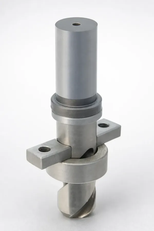
Third, check the vent flash and the gate velocity from the shot trace. Light flash on the vent land means the vent is open and the front reached it. No flash at all means the metal never got there, which is a fill problem, not a vent problem. Confirm the second-stage plunger velocity against the fill window.
Cold shut diagnosis checklist. Work through these in order and record each number in the process sheet:
- Fill time from the shot trace, against a 20 to 80 ms window for a 3 to 6 mm wall.
- Gate velocity, against 40 to 60 m/s for a 2 mm wall and 30 to 40 m/s as the lower limit.
- Gate area, after a 20 to 30 percent increase test.
- Biscuit thickness, held at 15 to 25 mm.
- Shot sleeve clearance, replaced above 0.25 mm.
- Die face temperature at the last-fill corner, 10 to 25 °C above the balance line.
- Vent depth 0.02 to 0.05 mm, spacing every 20 to 30 mm, land length 150 to 250 times the depth.
- Overflow count and depth, 1 to 3 pockets at 8 to 12 mm deep at the last fill.
- Metal temperature in the sleeve, 620 to 680 °C, checked at the pour.
- Seam position on the part, measured from the gate in millimetres.
Vents, Overflows and Last-Fill Corners
Venting is the cheapest fix on the list and the one most often cut too shallow. Cut vents 0.02 to 0.05 mm deep and space them every 20 to 30 mm around the last-fill periphery so the front exhausts air along the whole corner. Land length runs 150 to 250 times the vent depth, which puts a 0.03 mm vent on a 4.5 to 7.5 mm land, then a 0.5 to 1.0 mm relief.
Vents must be cut with a grinder or small end mill and re-checked with a feeler gauge. A vent that measured 0.03 mm at the bench and 0.01 mm after 2,000 shots has closed with condensed oxide, and the corner returns to a misrun with no change to any process setting.
Overflows do the heavier work. Add 1 to 3 overflow pockets at the last fill, 8 to 12 mm deep, so the cold front leaves the part and freezes in a pocket that is trimmed off. A weir of 0.5 to 1.0 mm keeps the pocket from robbing metal early in the fill, and the pocket volume should hold 15 to 25 percent of the part volume.
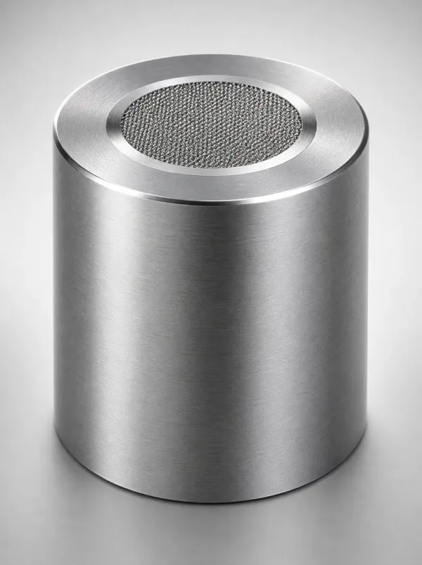
Place the vent and the overflow at the point the partial-shot study identifies, not where the CAD model suggests. A 10 to 20 mm misplacement puts the vent behind a dead zone and the corner still shorts, and a weir ground to 1.5 mm passes metal so early that the overflow fills before the cavity and stops venting.
Gate and Runner Fixes That Cut Fill Time
The gate is the lever with the largest effect on fill time. Widening a gate 20 to 30 percent in area cuts fill time 15 to 25 percent at the same plunger velocity, and on the 0.35 kg housing that is the difference between a 55 ms fill and a 43 ms one. Confirm the change with the flow calculation rather than by feel: cavity volume divided by gate area times gate velocity.
Runner design supports the gate. Keep the runner cross-section 40 to 60 percent larger than the gate area it feeds so the gate, not the runner, controls the flow. Hold a full-round or trapezoidal runner rather than a half-round, because a half-round runner has twice the wetted perimeter for the same area and loses 10 to 15 °C more over a 150 mm run. A sprue taper of 2 to 4 degrees and a cold slug well 8 to 12 mm deep below the sprue keep a cold plug out of the gate.
For a multi-drop die, balance the drops by area. A cavity fed by a runner 20 percent smaller than its neighbour fills 10 to 20 ms later and shuts cold while the others run clean. The full set of gate and runner rules, including fan, tangential and split-gate geometry for thin walls, sits in the guide to die casting gates and runners.
Thermal Fixes: Metal, Die and Shot Sleeve Temperatures
Thermal fixes are the second lever, and they need a narrower hand than most setters use. Raise the metal 10 to 20 °C or the die 15 to 30 °C at the far end, and stop there. Beyond a local solidification rate of 60 to 80 °C per second the metal stays fluid long enough to flash at the parting line and to shrink-porosity in the heavy sections, so the cure for a cold shut creates a flash and a porosity problem.
Heat the cold zone, not the whole die. A cartridge heater pair or an added oil circuit in the block that carries the last-fill corner holds that region 10 to 25 °C above the balance line without lifting the gate end, and it costs one afternoon against a 2 to 5 week die rebuild.
Preheat covers the start-up window. A die started at 90 to 120 °C will misrun for the first 30 to 50 shots, and those shots are scrap. Bring the die face to 180 to 220 °C before the first shot and the rate flattens from the first part; the sequence and heater sizing are covered in the guide to preheating and starting up a die casting die.
Vacuum Assist When the Fill Margin Runs Out
Vacuum assist is the last mechanical lever before a die redesign. Pulling the cavity to 100 to 200 mbar absolute before the shot removes the back pressure that slows the front, which buys 10 to 25 percent of the fill-time margin. On a thin-wall housing with a 0.8 to 1.5 mm wall, that margin is often the difference between a 3 percent and a 0.5 percent misrun rate.
Budget the cycle cost before the upgrade. A vacuum system adds 8 to 15 percent to cycle time on sealing, valve actuation and evacuation, and the die needs a sealed parting line and sealed ejector paths. The circuit design, valve timing and seal details are set out in the guide to vacuum-assisted die casting dies.
When a Cold Shut Can Be Accepted
Not every cold shut is a reject. A seam on a non-cosmetic, non-sealing rib, or an internal boss less than 1 mm deep, can pass when the pressure test holds and the section is clean at the fracture face. The deciding factors are function and customer standard, not the visual appearance of a line on the part.
Write the limit into the control plan. A worked limit sample is the only reliable way to hold a line: mark it with the seam location, the seam width in millimetres, the pressure-test result and the date, then store it with the die. A cold shut on a sealing flange, on a pressure-tight path, or on a surface that receives a powder coat at 180 to 200 °C is never acceptable, because it fails a test the customer will run.
Record the acceptance decision on the drawing, not in a shift note. DieStrike builds die-casting dies to IATF 16949 with flow and thermal simulation on the fill and the last-fill corner, +/-0.005 mm mold tolerance, +/-0.002 mm on EDM and jig grinding, HRC 62 heat treatment, 120+ machines and tier-1 references that include TE, Amphenol, Luxshare and Dongshan. The die casting mold service covers gate, overflow and vent design as one package so the last-fill corner is defined before the steel is cut.
Scrap Math: What an Incomplete Fill Costs
The metal cost of a misrun is small and the machine cost is not. A 0.35 kg casting at 2.4 USD per kg carries 0.84 USD of metal, and a 1.5 percent incomplete-fill rate adds 1.3 cents per good part. Add the shot that produced it, at a 40 to 60 s cycle on a cell that costs 60 to 90 USD per hour, and the true penalty lands at 2.5 to 3.0 cents per good part.
Then add the interventions. A 1.5 percent rate on a 500,000 part year is 7,500 rejected castings and 7,500 lost cycles, which is 300 to 380 hours of machine time that produced nothing, before the sorting and leak-test passes are counted.
The fix economics favour tooling. Vent cutting and an overflow pocket cost 8 to 20 hours of die work, a gate-area change 16 to 30 hours, and a thermal circuit split 12 to 24 hours. Set that against the annual scrap and the payback is usually inside one production month.
The Bottom Line
Cold shuts and misruns are a fill-time defect with a thermal signature. Read the fill time first and hold it in the 20 to 80 ms window for a 3 to 6 mm aluminium wall. Hold gate velocity at 40 to 60 m/s on a 2 mm wall. Keep the last-fill corner 10 to 25 °C above the balance line, with vents 0.02 to 0.05 mm deep every 20 to 30 mm and 1 to 3 overflow pockets at 8 to 12 mm deep. Diagnose with a partial-shot study and a thermal camera before touching the metal temperature, and the seam disappears without an unnecessary die rebuild.
DieStrike supplies die-casting dies and precision mold components from an IATF 16949 plant with 120+ machines, +/-0.005 mm mold tolerance, +/-0.002 mm on EDM and jig grinding, HRC 62 cavity heat treatment, standard components in 3 to 7 days and tool lead times of 2 to 5 weeks.
KEEP READING
Related Reading
Thin-Wall Die Casting Die Design
Wall sections from 0.8 to 2.0 mm, fill times under 60 ms and the thermal balance a thin housing needs.
Read articleArticleOverflows and Weir Vents in Die Casting
Overflow volume, weir thickness and vent location for the last-fill corner of a die-cast cavity.
Read articleArticleHot Chamber vs Cold Chamber Die Casting
Cycle, injection pressure and fill-time windows for zinc hot chamber against aluminium cold chamber.
Read articleServiceDie Casting Mold Manufacturing
IATF 16949 die-casting dies with thermal and flow simulation, vent and overflow design and 2 to 5 week lead times.
Read articleNEXT STEP
Ready to Start Your Mold?
Send us your element dimensions or part numbers — our team responds within 24 hours with pricing and lead time.

Written by
Ray ChanMold Buyer's Guide Author · Precision Mold Manufacturing Specialist. Ray helps global importers, distributors and OEMs source factory-direct molds and mold parts.