
How to Run a Mold Design Review: 12 Checks Before Steel
Table of Contents
A 14-cavity connector tool went to steel after a 40-minute phone call. The DFM report had flagged the gate land length, but nobody checked the shut-off angle against the 0.5 degree draft on the boss. Six weeks later the first trial flashed on nine cavities and left a 0.12 mm step at the parting line. Rework cost USD 9,800 and pushed the launch 21 days, on a tool that had already consumed its 2 to 5 week build window. The meeting that would have caught it takes one afternoon.
A mold design review is a freeze gate. It is the point where the buyer and the mold maker agree that the tool geometry, the steel, the mechanisms and the machine interface are fixed, and that any later change runs through a change order. It sits before steel cutting, well before the trial, and it is not the same as a DFM check. DFM asks whether the part can be molded. A design review asks whether this tool can be built, run, maintained and paid for.
The Snapshot
- Hold the review 3 to 7 days after quote acceptance. It must land before the cavity block is ordered, and cavity steel typically takes 2 to 4 weeks to arrive.
- Eight documents make the review pack. 3D model, 2D cavity drawing, parting line and insert plan, runner and gate layout, cooling circuit with flow numbers, ejection layout, mechanism simulation and the tolerance stack.
- Twelve checks decide the freeze. Parting line, draft, wall thickness, gating, venting, cooling, ejection, actions, steel and heat treatment, tolerances, machine interface and maintenance access.
- A change after freeze costs 3 to 5 times more once roughing is done. The same change costs 10 times or more after the trial, and typical industry figures put rework at USD 4,000 to 12,000 per round.
- The meeting runs 90 to 120 minutes. It closes with a signed minutes sheet, an engineering change order (ECO) number and a frozen revision letter such as Rev B.

Why a Design Review Is a Freeze Gate, Not a DFM Check
Buyers often treat the two events as one. They are not. A DFM review works on the part: wall thickness, draft angle, radii, ribs, bosses, gate vestige allowance and material choice. A design review works on the tool: parting line, shut-off lands, insert split, mechanism travel, cooling circuits, steel grade and heat treatment, tolerance stack and machine interface.
Part-level changes are cheap. Moving a rib 0.3 mm costs perhaps one hour of CAD time and one exchange of files. Tool-level changes are not, because each one reaches into steel that has already been ordered, machined or heat treated. That is why the design review is a gate with a signature, not a courtesy call.
The freeze protects the lead time. A precision injection mold takes 2 to 5 weeks from released design to trial-ready tool at a shop running DFM feedback inside 24 hours. Every unfrozen decision during those weeks competes with machining capacity. A gate that closes all open questions on one day keeps the schedule intact. A loose gate stretches the same tool to 8 weeks without any single dramatic failure.
The gate has an owner. In most programs the buyer's tooling engineer owns the review, and the mold maker's project engineer runs the agenda. Both sign. Once signed, the drawing revision is locked, the CAM programmer works to it, and any deviation starts with an ECO number rather than a verbal instruction over chat.
The gate is not a substitute for the trial. A design review approves geometry. The trial proves it. A mold trial runs in stages, from T0 functional checks at 20 to 50 shots through CMM verification at ±0.005 mm and on to first article inspection. The review sets the dimensions the trial will measure. Without the review, the trial discovers design errors at the most expensive moment in the program.
When to Hold the Review: Timing, Inputs and Attendees
Timing drives value. A review held too early has nothing to review. A review held after the cavity block is on order can only accept what is already paid for. The usable window is short and it starts when the purchase order lands.
Target 3 to 7 days after quote acceptance. That window gives the mold maker enough time to build the 3D model, run the parting line study and complete a flow simulation. It also leaves room for one follow-up session before steel is released. Programs that compress the review to a single 30-minute call usually pay for it in the change-cost curve described later.
Stop the steel order, not the CAD work. Standard mold components such as ejector pins, sprue bushings, leader pins and springs ship in 3 to 7 days and can be ordered early without risk. Cavity and core blocks, inserts, sliders and hot runner manifolds should wait for the freeze, because those carry the geometry that the review approves.
Invite six roles. The mold designer, the shop project engineer, the buyer's tooling engineer, the process engineer who will run the trial, the quality engineer who will read the CMM report, and the hot runner or standard parts supplier when the tool uses one. Missing the process engineer is the most common omission, and it is the role most likely to catch an ejection or cooling problem.
Run the agenda in a fixed order. Part and material, parting line, gating, cooling, ejection, mechanisms, steel and heat treatment, tolerances, machine interface, maintenance. A fixed order matters because decisions cascade. Changing the parting line after the gate layout is approved reopens the gate layout.

The Review Pack: 8 Documents Before Steel
A review without documents becomes a presentation. Both sides need the same eight items 48 hours before the meeting so the review starts from reading, not from explaining. Each item carries a hard number that the review either confirms or rejects.
1. 3D model and 2D cavity drawing. The 3D model shows the tool assembly at the frozen revision. The 2D cavity drawing carries the critical dimensions, datum scheme and GD&T frame. Mold size tolerance is typically held to ±0.005 mm on cavity geometry, with insert fits at H7/h6 and shut-off land widths of 3 to 6 mm.
2. Parting line and insert plan. Show where the parting line runs on the part, how the shut-offs seal, and which features sit in inserts. Insert splits add cost, so each insert needs a reason such as a sharp corner, a deep rib, a wear area or a heat treatment difference. Typical insert count for a mid-size housing runs 3 to 8 pieces per side.
3. Runner, gate and hot runner configuration. Gate type, gate diameter and land length, runner diameter, balance across cavities and drop positions. A cold runner for an unfilled resin runs a gate diameter of 0.8 to 2.0 mm depending on wall thickness, with land length of 1.0 to 1.5 mm. A hot runner needs drop spacing, manifold expansion allowance and thermocouple zoning on the drawing.
4. Cooling circuit layout with flow numbers. Circuit path, diameter, baffle or bubbler positions, pitch between channels and the flow calculation per circuit. A typical rule is 20 to 30 mm channel pitch with 8 to 12 mm channel diameter for a 2 to 4 mm wall, and Reynolds number above 10,000 for turbulent flow. Turbulent water transfers heat far better than laminar flow, and the drawing should state the target flow rate in litres per minute.
5. Ejection layout and stroke. Where the ejector pins, sleeves and blades sit, how far they stroke, and what the part touches. Reviewers check pin density against part stiffness, taper on sleeve tips, and the stroke against part height plus a clearance margin of 5 to 10 mm. Ejector plates need room to travel without bottoming on the machine knock-out.
6. Slide, lifter and mechanism simulation. Every side action needs a motion study showing travel, angle, lock-up and return. Undercut release angles above 10 degrees carry more wear, and slides need positive locking blocks plus a spring or hydraulic return. The pack should name the mechanism stroke in millimetres and the estimated cycle cost in seconds.
7. Steel and heat treatment specification. Named grade per component, hardness target, surface treatment and the certificate standard. A typical pack for an engineering resin shows P20 for the mold base at HRC 28 to 32, and a stainless or H13 insert at HRC 48 to 54 with optional nitriding to HRC 62 on wear surfaces. Each grade should carry an EN 10204 3.1 material certificate requirement.
8. Tolerance stack and critical dimension list. The stack analysis shows how part tolerances translate into cavity dimensions, and the list names the 10 to 25 dimensions that will be measured at trial. A part tolerance of ±0.05 mm typically compresses to about ±0.015 mm on the cavity when the stack is allocated worst-case across the tool, and the review must agree on the allocation before steel.

The 12-Point Mold Design Review Checklist
This is the working list. Walk it in order, one line at a time, and record a decision on every row. A row marked open is a row that will cost money later, so either close it in the meeting or assign a date and an owner before the meeting ends.
| # | Check | What to Confirm | Typical Value or Limit | Cost If Missed |
|---|---|---|---|---|
| 1 | Parting line | Placement against part function, shut-off land width, seal direction | Land 3 to 6 mm, shut-off angle 5 to 10 degrees | Visible witness line, flash, insert rework |
| 2 | Draft | Every wall in the pull direction, textured surfaces, deep ribs | 1 to 2 degrees standard, 3 to 5 degrees on texture, 0.5 degree minimum | Scuffing, drag marks, manual part release |
| 3 | Wall thickness | Nominal wall, transitions, rib-to-wall ratio, boss wall | Ribs 0.5 to 0.6 of wall, flow length to thickness under 200:1 | Short shots, sink marks, warpage |
| 4 | Gating | Gate type, diameter, land length, position against weld lines and jetting | Gate 0.8 to 2.0 mm, land 1.0 to 1.5 mm | Weld line at a functional face, gate blush, jetting |
| 5 | Venting | Vent depth, land length, placement at last fill and weld lines | 0.01 to 0.03 mm deep, 2 to 3 mm land on the parting line | Burn marks, dieseling, short shots at speed |
| 6 | Cooling | Circuit pitch, baffles and bubblers, flow rate per circuit, seal plugs | Pitch 20 to 30 mm, channels 8 to 12 mm, Reynolds above 10,000 | Long cycles, differential shrinkage, warpage |
| 7 | Ejection | Pin layout, pin size against local geometry, stroke, plate travel | Stroke of part height plus 5 to 10 mm, pin load under local yield | Pin marks, sticking parts, bent pins |
| 8 | Mechanisms | Slides, lifters and angle pins: travel, lock-up, return, clearance | Lifter angle 5 to 15 degrees, slide lock block positive | Die crash, undercut tearing, delayed cycle |
| 9 | Steel and heat treatment | Grade per component, hardness target, coating, material certificate | Inserts HRC 48 to 54, wear surfaces to HRC 62, EN 10204 3.1 | Early wear, galling, corrosion, rejected steel |
| 10 | Tolerances | Stack analysis, critical dimension list, datum scheme, inspection plan | Cavity ±0.005 mm, insert geometry ±0.002 mm | Trial failure, weld-and-remachine loops, late ECOs |
| 11 | Machine interface | Locating ring, clamp plate, ejector pattern, nozzle radius, tonnage | Ring fit H7, plate thickness matched to platen slots, SPI pattern | Tool will not mount, knock-out conflict, press downtime |
| 12 | Maintenance access | Insert removal, water fitting access, lifting points, spare part list | Insert pull-out in under 30 minutes, lifting eyes rated to tool mass | Pull-the-tool repairs, long unplanned downtime |
← swipe to scroll →
Table note: Values are typical industry figures for mid-size injection molds running engineering resins. Exact limits follow the resin datasheet, the customer drawing and the machine specification.
Two of the twelve rows deserve a second pass in every program. Tolerance allocation is where the review earns its money. Wall thickness and venting are where a good review catches problems that a flow simulation will only report as symptoms.
Machine Interface Verification: 4 Fit Points
A tool that does not mount stops the program regardless of how good the cavity is. Verify the interface against the actual press that will run the trial, not against a family of presses. A 12-item compatibility check belongs in the pack, but four points cause most of the damage.
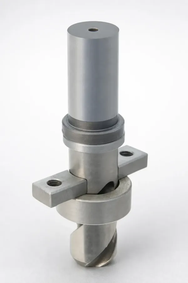
Locating ring and nozzle radius. The ring centres the tool on the platen and must match the press bore, usually on an H7 fit at 100, 120, 150 or 180 mm diameter. The sprue bush radius must seal against the nozzle without crushing it. A mismatch of 0.5 mm shows up as flash around the sprue bush and a cold slug that stalls the cycle.
Top clamp plate and platen slots. Clamp plate thickness must match the platen slot width within about 0.5 mm, and the plate width must clear the slot stops. Tools that need spacers to clamp safely derate the effective tonnage and invite plate flex under a 0.7 to 0.9 cavity pressure ratio.
Ejector pattern and knock-out. Ejector holes must line up with the press knock-out pattern, including the centre hole for a sprue puller. Check ejector stroke against the machine's maximum knock-out travel and against any robot or conveyor envelope. Automation grippers need 30 to 80 mm of clear space below the parting line.
SPI utility connections. Water inlets and outlets, hydraulic ports for valve gates or slides, and air lines must all map to the SPI pattern. A review that names each circuit is also the review that catches a 3-circuit mismatch against a controller manifold. The mold safety and buy-off checklist covers the full connection set and the sign-off format.
Mold Flow Result Verification: Fill, Pack, Warp
Most shops run a filling study on any tool above a 4-cavity layout or any part below a 1.2 mm wall. The review should read the results rather than accept the file. Three outputs matter and each one maps to a design decision that must already be frozen or changed now.
Fill: pressure and balance. Check the pressure at the end of fill against the machine capability with a margin. A tool that needs 120 MPa of cavity pressure on a press rated for 150 MPa has no process window left for variation. Check the cavity-to-cavity imbalance too, with most programs targeting under 5 percent at a balanced runner and under 10 percent as an acceptable ceiling.
Pack: gate freeze and volume shrinkage. Confirm where the gate seals and whether packing reaches the far end of the part before that point. A gate that freezes too early leaves a 0.5 to 1.5 percent volumetric shrinkage deficit in the thick section, which becomes a sink mark 0.05 to 0.15 mm deep. The fix belongs in the gate diameter or the wall transition, and both are still free before steel.
Warp: differential shrinkage and cooling balance. A warp plot with more than about 0.3 mm of out-of-flat over a 100 mm span on a flat cosmetic face will not pass inspection. Trace it to circuit imbalance, a hot spot at an insert, or an asymmetric gate. Flow analysis is worth paying for on tight-tolerance parts, and the mold flow analysis guide sets out when the spend earns a return.
Cross-check the flow file against the design. If the simulation used a 1.5 mm wall and the drawing says 1.8 mm, the pressure numbers are invalid. Record the simulation inputs and the software version in the minutes so the accepted result can be reproduced at the trial.
Review Outputs: Minutes, ECO and the Frozen Revision
A review that ends without paperwork did not happen. The output set is small, and every item must exist before the CAD file is released to CAM. Two days later nobody remembers what was agreed verbally.
Meeting minutes with a decision per row. Each of the 12 checklist rows gets a status: accepted, accepted with note, changed, or open with an owner and a date. A typical review produces 5 to 20 action items, and most programs close all of them within 3 working days.
ECO numbers for every change. A change order records what changed, why, who approved it and what it does to cost and schedule. Even a free change gets an ECO, because the ECO log is the audit trail that a customer or a quality auditor will ask for. Programs running IATF 16949 documentation typically keep the ECO log with the tool file for the life of the mold.
A frozen revision letter. The released drawing set carries a revision, such as Rev B, and the number is quoted in every later email about the tool. A drawing without a revision cannot be frozen, because there is nothing to compare a change against.
An updated review pack. The eight documents are reissued at the frozen revision, and the pack becomes the reference for the trial. When the trial measures a dimension, the value is compared against the dimension that the review accepted, not against whatever the CAD file says that week.
A distribution list. Minutes go to the mold designer, the CAM programmer, purchasing, quality and the buyer's tooling engineer on the same day. If the CAM programmer is not on the list, the frozen revision may not reach the machine.
Change Control: What a Change Costs After Freeze
Freeze does not mean nothing can change. It means a change now has a price, a route and a signature. That discipline is what stops a tool from being redesigned three times while it is being machined, which is the most common way a 2 to 5 week lead time becomes 9 weeks.
The cost curve is steep and predictable. A change made while the design is still on screen costs engineering hours only. The same change after rough machining means rework on heat-treated or near-net steel, plus re-verification. After the trial, the tool must come off the press, and the program absorbs both rework and press time.
| Stage of Change | Relative Cost | Typical Schedule Impact | What Rework Involves |
|---|---|---|---|
| Before steel is cut | 1x (baseline) | 0 to 2 days | CAD edit, revised drawing, reissued review pack |
| After rough machining | 3 to 5x | 3 to 10 days | Weld or recut of inserts, EDM rework, re-heat treatment |
| After finish machining and heat treatment | 5 to 8x | 1 to 3 weeks | New insert, polish, texture re-match, re-fit in cavity |
| After the trial (post-T1) | 10x or more | 2 to 5 weeks | Tool off press, dimensional rework, new trial run, fresh CMM report |
← swipe to scroll →
Table note: Relative cost multipliers are typical industry figures for mid-size injection molds and exclude the buyer's own launch delay. Absolute rework rounds commonly land between USD 4,000 and 12,000 each.
Route every change through the same three questions. What does it cost, what does it do to the date, and who accepts the risk. If a change touches the parting line, the cooling layout or the tolerance allocation, it earns a second short review with the same attendees. If it touches only a cosmetic detail such as a texture callout, it can move on a written approval.
Charge back on the correct party. A change driven by a customer part revision is a customer cost. A change driven by a mold design error, such as an insert split that will not release, is the mold maker's cost. Naming that split in the minutes prevents the argument that otherwise arrives with the invoice.
Sign-Off and Release: Buy-Off Conditions
Sign-off is a short ceremony with a heavy consequence. Once the minutes are signed, the tool is released to CAM and the steel is ordered. The conditions for that signature should be written down before the meeting, not negotiated during it.
Six conditions gate the release. All 12 checklist rows carry a decision. The review pack is reissued at the frozen revision. The tolerance stack is allocated and the critical dimension list is named. The machine interface is verified against an identified press with a serial number or asset tag. Steel grades and hardness targets are written on the drawing with a certificate standard. The ECO log is open and the minutes are distributed the same day.
Three items cannot stay open. The parting line, the gating layout and the tolerance allocation decide the shot. A tool released with any of those three open has no frozen geometry, and the CAM programmer will make the decision by default. If they cannot be closed in the meeting, hold the release and reconvene within 2 working days.
The signature set matches the program. For a standard commercial mold, the buyer's tooling engineer and the mold maker's project engineer both sign. For an automotive program running IATF 16949 documentation, the supplier's quality function signs as well, because the review minutes become part of the tool record that supports later PPAP submission.
Release leads straight into the build and the trial. After sign-off, the cavity blocks are ordered and the tool enters the 2 to 5 week build window. Standard components such as ejector pins, sprue bushings, leader pins and springs ship in 3 to 7 days and rarely gate the schedule. The review then hands the trial a dimension list rather than a question list, which is why a disciplined freeze usually cuts one full trial round off the program.
Carry the frozen numbers into inspection. The tolerance allocation agreed in the review becomes the basis for the first article file, and every measured value is compared against it. When the allocation is loose, the trial fails on paper. When it is realistic, the trial confirms the design and the program moves to production sampling. A buyer who wants the arithmetic behind that allocation should read the guide on mold tolerance stack-up before the meeting.
How a Buyer Runs the Review With the Mold Maker
A buyer controls two things that decide whether the review produces value: what arrives 48 hours before it, and how hard the questions land inside it. Both are cheap. Neither is common.
Send the inputs early. The final 3D part file, the 2D drawing with GD&T, the material grade with the datasheet, the press list with tonnage and platen data, the annual volume, the target mold life in shots, and the quality standard the parts must meet. A mold maker with a complete input set can return DFM feedback inside 24 hours and arrive at the review with a finished study instead of a sketch.
Ask for the number behind every statement. When the answer to a cooling question is that the layout is standard practice, ask for the pitch in millimetres and the flow rate per circuit. When gating comes up, ask for the gate diameter and the land length. Reviews get much shorter when opinions have to arrive with values attached.
Push on the interface and the maintenance plan. Confirm the locating ring diameter and fit, the clamp plate thickness, the ejector pattern and the SPI connection list. Then ask how an insert comes out and how long that takes. Anything above 30 minutes for a wear insert is a maintenance cost that repeats for the life of the tool. The mold to machine compatibility checklist gives the full fit list to walk through.
Close the meeting with three confirmations. Confirm the frozen revision letter, confirm that the minutes will reach you within 24 hours, and confirm the next milestone date for the first trial. A review that ends without those three items tends to be repeated.
Keep the DFM and the review separate in your own files. The DFM checklist covers the part-level items that belong before the quote. The design review covers the tool. Mixing them is the fastest way to let a parting line decision slide because the meeting ran out of time on wall thickness.
6 Ways Mold Design Reviews Fail
Most failed reviews fail for reasons that have nothing to do with engineering skill. They fail on process, and the same six patterns repeat across programs and industries.
1. No pack, no agenda. The meeting becomes a presentation, and the decisions are made from memory. A review without the eight documents has no evidence to check, and rows get marked accepted without a number behind them.
2. The wrong attendees. Designers and buyers attend, the process engineer and the quality engineer do not. Cooling, ejection and inspection problems then surface at the trial, where a cooling fix costs 3 to 5 times more than at the gate.
3. Reviewing the part instead of the tool. Forty minutes on wall thickness leaves twenty minutes for parting line, mechanisms and the interface. The part was already reviewed at DFM stage. The tool is new information.
4. Accepting a simulation without checking its inputs. A flow study run on a 1.5 mm wall when the drawing says 1.8 mm produces confident, useless numbers. The review should record the mesh, wall thickness and material grade used in the run.
5. No revision control after the review. Changes arrive by chat message, the CAM programmer works to the older file, and the trial measures a hybrid tool. An ECO number per change closes this gap for the cost of ten minutes of admin.
6. Compressing the review to protect the schedule. A 30-minute call on a 14-cavity tool usually costs 3 to 4 weeks later. The review is the cheapest hour in the program, and cutting it moves cost into the phase where every fix runs 3 to 10 times higher.
Mold Design Review FAQ
Q1. How long does a mold design review take?
Plan for 90 to 120 minutes with all six roles present, plus 3 working days of follow-up to close open items. A single-cavity prototype tool can finish in 45 to 60 minutes, and a 32-cavity hot runner tool with slides often needs two sessions.
Q2. When exactly should the design freeze happen?
Target 3 to 7 days after quote acceptance, and always before the cavity block is ordered. Cavity steel commonly takes 2 to 4 weeks to arrive, so a review that slips past the block order has already surrendered the leverage it was meant to create.
Q3. What does a change cost after the freeze?
Typical industry figures put a change at 1x before steel, 3 to 5x after rough machining, 5 to 8x after finish machining and heat treatment, and 10x or more after the trial. A single rework round on a mid-size mold commonly lands between USD 4,000 and 12,000.
Q4. How many documents should the review pack contain?
Eight: the 3D model and 2D cavity drawing, the parting line and insert plan, the runner and gate layout, the cooling circuit with flow numbers, the ejection layout with stroke, the mechanism motion study, the steel and heat treatment specification, and the tolerance stack with the critical dimension list.
Q5. Does the review replace the mold trial?
No. The review approves geometry and the trial proves it. A staged trial starts with T0 functional checks at 20 to 50 shots, moves to CMM verification at ±0.005 mm, and closes with first article inspection on 50 to 500 sample parts before the tool is released to production.
The Bottom Line
The review costs one afternoon and eight documents. Skip it and the same decisions return as rework at 3 to 5 times the cost, or 10 times after the trial. Freeze the geometry, sign the minutes, and the trial measures a design rather than a guess. DieStrike builds IATF 16949 precision molds with ±0.005 mm mold accuracy, ±0.002 mm part geometry and DFM feedback inside 24 hours. Send your part drawing and press list through our contact page.
KEEP READING
Related Reading
The DFM Checklist: 7 Things to Check Before Your Mold Order
The part-level checks that belong before the quote, and the seven fields a DFM request must include to get usable feedback in 24 hours.
Read articleArticleHow to Calculate a Mold Tolerance Stack-Up
Worst-case and statistical stack methods, the 1.5x safety factor on cavity steel and how a 0.05 mm part tolerance lands as 0.015 mm in the tool.
Read articleArticleHow to Run a Mold Trial: T0, T1, T2 and First Article Approval
The staged trial sequence that turns a frozen design into signed dimensional data, from 20 to 50 T0 shots through FAI sample quantities.
Read articleServiceMold Design & DFM
Mold flow analysis, tolerance stack-up review and steel selection for tight-tolerance programs, with engineering feedback inside 24 hours.
Read articleNEXT STEP
Ready to Start Your Mold?
Send us your element dimensions or part numbers — our team responds within 24 hours with pricing and lead time.

Written by
Ray ChanMold Buyer's Guide Author · Precision Mold Manufacturing Specialist. Ray helps global importers, distributors and OEMs source factory-direct molds and mold parts.