
Fillet vs Chamfer: When to Use Each in Mold Design
Table of Contents
A 0.2 mm sharp corner in a molded bracket is free to draw and expensive to own. That corner raises local stress to roughly three times the nominal level — a stress concentration factor around Kt 3 — and under repeated snap-fit assembly, vibration, or a single hard drop, the crack starts exactly there. The tool mirrors the risk: a sharp steel corner at the parting line chips under clamp tonnage and thermal cycling, and one chipped corner means weld repair, re-machining, and days of lost production.
The fillet vs chamfer question is one of the most common corner decisions in mold design, and it is usually asked after the fact — when a stress analysis flags the geometry, or after molded parts crack at a radius that was never specified. Both features remove a sharp edge, but they are not interchangeable. A fillet is a radius, a chamfer is a bevel. They concentrate stress differently, they are cut differently in the tool, and they cost different amounts of machining time.
This guide is for mold buyers, product engineers, and mold engineers who need a defensible answer: which corner treatment goes where, what numbers to put on the drawing, and how the mold shop will actually machine the feature. The stress concentration factors and dimensional rules below are typical engineering values for injection-molded plastic parts and production molds — starting points to validate against your load case and material, not guarantees.
The Snapshot
- A sharp internal corner carries a stress concentration factor of about 3× (Kt ≈ 3); a fillet of radius ≥ 0.5× wall thickness drops it to roughly 1.5-2× — typical values for a corner under tension.
- Minimum fillet rule for plastic parts: internal corner radius ≥ 0.5 mm or ≥ 0.5× wall thickness, whichever is larger; external corners run 0.25-0.5× wall thickness.
- Wall thickness transitions blend at a maximum 3:1 ratio; a step without a fillet is a molded-in stress raiser and a knit-line trap.
- Chamfers are for assembly: lead-in angles of 20-45° (30-45° typical) and edge breaks of 0.2-0.5 mm × 45° on handled or cosmetic edges.
- Draft needs 0.5-1° per side minimum — 0.5° on short polished walls, 1° standard, 1.5-2° where the cavity is textured.
- Mold-side reality: fillets are cut with ball-end mills of R0.5-R3 mm or sunk by EDM; an internal radius smaller than the tool radius forces a tool change or a spark-erosion operation — both slower and more expensive.
- DieStrike reviews corner geometry during a 24-hour DFM pass and verifies critical radii by CMM on every mold we ship.
Why Edge Geometry Matters
Corner geometry is where two failure modes meet — part-side stress concentration and tool-side edge chipping. Neither shows up on a nominal-dimension drawing. Both show up in production and in the field, and both are decided the day the corner is drawn or left sharp.
On the part side, every molded plastic part carries molded-in stress from shrinkage and ejection, and service loads stack on top of it. A sharp corner multiplies the combined stress locally — typically 3× or more (Kt ≈ 3) for an unradiused internal corner — and plastics are notch-sensitive: cracks initiate at the geometric discontinuity and grow from there. Drop-test failures on housings, cracks at snap-fit bases, and fatigue cracks at boss roots share one root cause: a corner that concentrates stress instead of spreading it. The fix is cheap on the drawing and expensive after the fact. Adding a 0.5 mm radius costs nothing in CAD, while a crack found after 10,000 cycles means a tool modification, revalidation, and possibly a field recall. If the part is load-bearing, the corner geometry belongs in the stress review before steel is cut — the same discipline covered in our how to design for moldability guide.
On the tool side, sharp edges in steel are the weak points of a mold. A cavity edge or parting-line corner with no radius has almost no load-bearing cross-section. Under clamp tonnage — typically 2-5 tons per square inch of projected area for production molds — and the thermal cycling of every shot, these edges chip. A chipped corner on a visible part means flash or witness marks; a chipped edge in a critical seal-off area means leaking flash that can take the mold down. Repair is weld, re-machine, and re-polish — on hardened steel like S136 at 48-52 HRC or H13 at 46-52 HRC that is a bench operation plus revalidation, and days of lost production. Mold buyers usually see the invoice for this in the tool-maintenance line, not in the original quote.
The engineering rule that follows is simple: if a corner carries load, give it a radius; if it only needs protection from burrs and chipping, give it a chamfer. The sections below put numbers on both sides of that rule.
Fillet vs Chamfer: The Core Difference
A fillet is a concave radius that replaces a sharp corner with a continuous curve — the classic example is the rounded junction between a boss and a wall. A chamfer is a straight bevel cut across the corner at a fixed angle, typically 45° for edge breaks and 20-45° for assembly lead-ins. An edge break is the small chamfer applied purely to remove burrs and sharp edges — usually 0.2-0.5 mm × 45° — and it is the cheapest corner treatment on the drawing.

The difference that matters in engineering is stress flow. A fillet spreads the load along a smooth curve; a chamfer redirects it along two straight segments and leaves a slope discontinuity at each end. Both beat a sharp corner, but a fillet beats a chamfer at the same nominal size — typical stress concentration factors run 1.5-2 for a proper fillet versus 2-2.5 for a 45° chamfer on the same corner.
| Aspect | Fillet | Chamfer | Edge break |
|---|---|---|---|
| Definition | Concave radius blending two surfaces | Straight bevel at a fixed angle | Small chamfer for deburring |
| Geometry | Continuous curve, radius R | Straight line, angle + width | 0.2-0.5 mm × 45° |
| Stress concentration (typical Kt) | 1.5-2 with R ≥ 0.5× wall | 2-2.5 | Negligible — cosmetic |
| Mold machining | Ball-end mill R0.5-R3 mm, EDM, polish along radius | Chamfer mill, EDM, or hand stone | Hand stone or chamfer mill pass |
| Cost impact | Low when radius matches standard tooling; rises below R0.5 mm | Low; single pass with standard tool | Negligible |
| Primary job | Spread stress, strengthen corners | Assembly lead-in, edge protection | Deburr, protect steel edge |
← swipe to scroll →
Kt values are typical for a corner under tension; actual values depend on load direction, part geometry, and material.
Notice what the table does not say: chamfers are not a shortcut for fillets on load-bearing corners. If the corner carries bending, impact, or repeated assembly load, the radius does the structural job and the chamfer does the assembly job — often both on the same feature, with a fillet at the root and a lead-in chamfer at the opening.
Stress Concentration: The Engineering Case for Fillets
The case for fillets rests on the stress concentration factor Kt, the ratio of peak local stress to nominal stress: Kt = σmax / σnom. For a corner in tension, geometry sets Kt almost entirely — the sharper the discontinuity, the higher the peak. This is why two parts made of identical material can behave completely differently: the corner, not the resin, decides where it breaks.
Typical values for molded-plastic corners: an unradiused sharp internal corner runs Kt ≈ 3 or higher. A fillet with radius equal to 0.5× wall thickness drops it to roughly 1.5-1.7. A fillet of only 0.1× wall thickness still sits near 2.5 — the radius size matters as much as the presence of a radius. A 45° chamfer lands around 2-2.5: better than sharp, but well short of a proper fillet.
| Corner geometry | Typical Kt (corner in tension) | Design guidance |
|---|---|---|
| Sharp internal corner, no radius | ≈ 3+ | Avoid on any loaded feature; crack initiation site |
| Fillet, R = 0.1× wall thickness | ≈ 2.5 | Marginal; better than sharp but below target |
| Fillet, R = 0.25× wall thickness | ≈ 2 | Acceptable for lightly loaded corners |
| Fillet, R = 0.5× wall thickness | ≈ 1.5-1.7 | Design target for load-bearing corners |
| 45° chamfer | ≈ 2-2.5 | Fine for assembly and edge protection; not a structural fix |
← swipe to scroll →
Values from typical published stress concentration charts for rounded and beveled corners under tension.
Why the fillet wins: a radius is a continuous curve, so the load path bends gradually and the peak stress stays low and predictable. A chamfer is two straight lines meeting the wall at a slope discontinuity — each end of the chamfer is itself a mini-corner. The chamfer lowers the peak below a sharp corner, but it does not remove the discontinuity that drives the peak.
Where this bites in practice: snap-fit lances, boss roots, rib-to-wall junctions, living-hinge bases, press-fit hubs, and anywhere the part sees repeated loading or impact. A product engineer who specs a 0.2 mm edge break on a snap-fit root is buying a crack that shows up at a cycle count instead of in the drawing review. Spec the radius.
Mold Manufacturing: How Each Edge Is Cut
The mold shop's view of corner geometry is a toolpath question. Fillets in the CAD model are cut with ball-end mills — the internal corner radius cannot be smaller than the tool radius, and standard mold-shop ball mills run R0.5-R3 mm. Match the drawn radius to a standard tool radius and the fillet is a single finishing pass; spec R0.8 mm and the shop either burns a custom electrode or machines with an undersized tool — slower, and the invoice shows it.
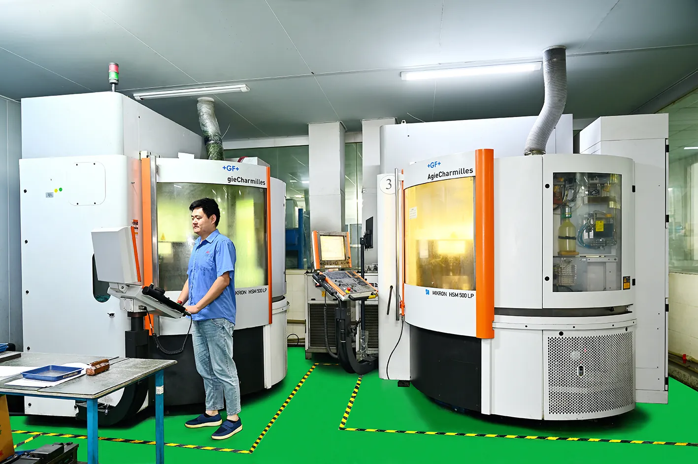
Sharp internal corners — square pockets, lettering corners, fine features below R0.5 mm — cannot be reached by a round cutter, so they are sunk by EDM. The electrode is machined to the negative of the corner, and spark gap plus electrode wear are compensated in the program. On the DieStrike floor, Sodick machines hold finishes to Ra 0.02 µm, and the EDM corner is hand-polished afterward to blend. EDM adds an operation, an electrode, and bench time — typically more cost than a standard-radius milled fillet.

Chamfers are cheaper to cut. A chamfer mill or a standard end mill at 45° cuts the bevel in one pass, and small edge breaks are often done with a hand stone at the bench during fitting. The cost ranking runs from chamfer or edge break at the cheap end, through standard-radius fillets, to custom-radius fillets and EDM corners at the expensive end. None of these are large line items on a mold quote; the point is that corner decisions made on the drawing compound into machining and finishing time, and a DFM pass catches the expensive ones before steel is cut. That is the sequence we follow on every injection mold manufacturing project, from design through delivery.
Fillet Rules for Plastic Parts
For plastic parts, fillet rules exist to protect both the part and the tool. The two-number rule: internal corner radius ≥ 0.5 mm or ≥ 0.5× wall thickness, whichever is larger. On a 2 mm wall, that is a 1 mm radius; on a 1 mm wall, the 0.5 mm floor applies. External corners can run 0.25-0.5× wall thickness. The table below converts the rule to practical drawing values.
| Wall thickness | Minimum internal corner radius (0.5× wall, floor 0.5 mm) | Standard ball-mill match |
|---|---|---|
| 1.0 mm | 0.5 mm | R0.5 mm |
| 1.5 mm | 0.75 mm | R0.75 mm |
| 2.0 mm | 1.0 mm | R1.0 mm |
| 2.5 mm | 1.25 mm | R1.25 mm |
| 3.0 mm | 1.5 mm | R1.5 mm |
← swipe to scroll →
Radii rounded to standard ball-end mill sizes so the fillet machines in a single finishing pass.
Wall thickness transitions follow the same logic at a larger scale. A step from 2 mm to 1 mm wall without a blend is a stress raiser and a knit-line trap; the design rule is a maximum 3:1 transition ratio — the thin section should be at least one-third of the thick section — blended with a fillet, not a step. Where a 3:1 ratio is not possible, the fillet itself carries the load transition, and the blend radius becomes a structural feature, not a cosmetic one.
Rib and boss bases get 0.25-0.5× their own thickness at the root. The radius is a compromise: too small and the root concentrates stress; too large and the boss or rib thickens locally, pulls material, and sinks the opposite surface. On visible surfaces, keep the root radius at the low end — around 0.25× rib thickness — and let texture or a back-side location hide the sink.
Mold-side execution: the machined radius is blended and polished along the curve. Polish marks that run across a radius read as stress risers on glossy parts, so finishing follows the contour, and critical radii are verified by CMM before the mold ships.
Chamfer Rules for Plastic Parts
Chamfers are specified for three jobs: assembly lead-in, edge protection, and draft assistance. Assembly lead-ins are the most common — a chamfer of 20-45° (30-45° typical) at the mouth of a hole or on the leading edge of a snap-fit part guides assembly and prevents edge shaving during insertion. The angle is a compromise: steeper angles self-locate faster but catch on misalignment, while 20° keeps insertion forces low. 30-45° is the practical band for most molded parts.
Edge breaks are the small chamfer that protects corners: 0.2-0.5 mm × 45° on edges that are handled, assembled, or visible. They remove burrs and sharp edges — a 0.2 mm burr is a cut hazard in a hand-held product and a stress-raiser on a mating part. On the mold side, the same 45° break on a cavity edge protects the steel from chipping, which is why you will find edge breaks on mold drawings that the part never asks for.
Draft angles are chamfers in the third dimension — the taper on walls that lets the part release from the cavity. Minimum draft is 0.5-1° per side: 0.5° on short polished walls, 1° standard, 1.5-2° where the cavity surface is textured, and roughly 1° per 25 mm of depth as a rule of thumb for deep ribs and bosses. Draft is not optional geometry — it is the release angle the mold depends on, and a wall drawn parallel to the draw direction without draft gall the cavity on ejection. The interactions between draft, texture, and ejection are covered in detail in our 9 draft angle mistakes that kill moldability guide.
Chamfer dimensions stay small relative to the wall: lead-in chamfers run 0.3-1 mm wide depending on part size, and edge breaks 0.2-0.5 mm. A chamfer wider than half the wall on a structural edge starts acting like a notch — keep it proportional.
Parting Line and Textured Surfaces
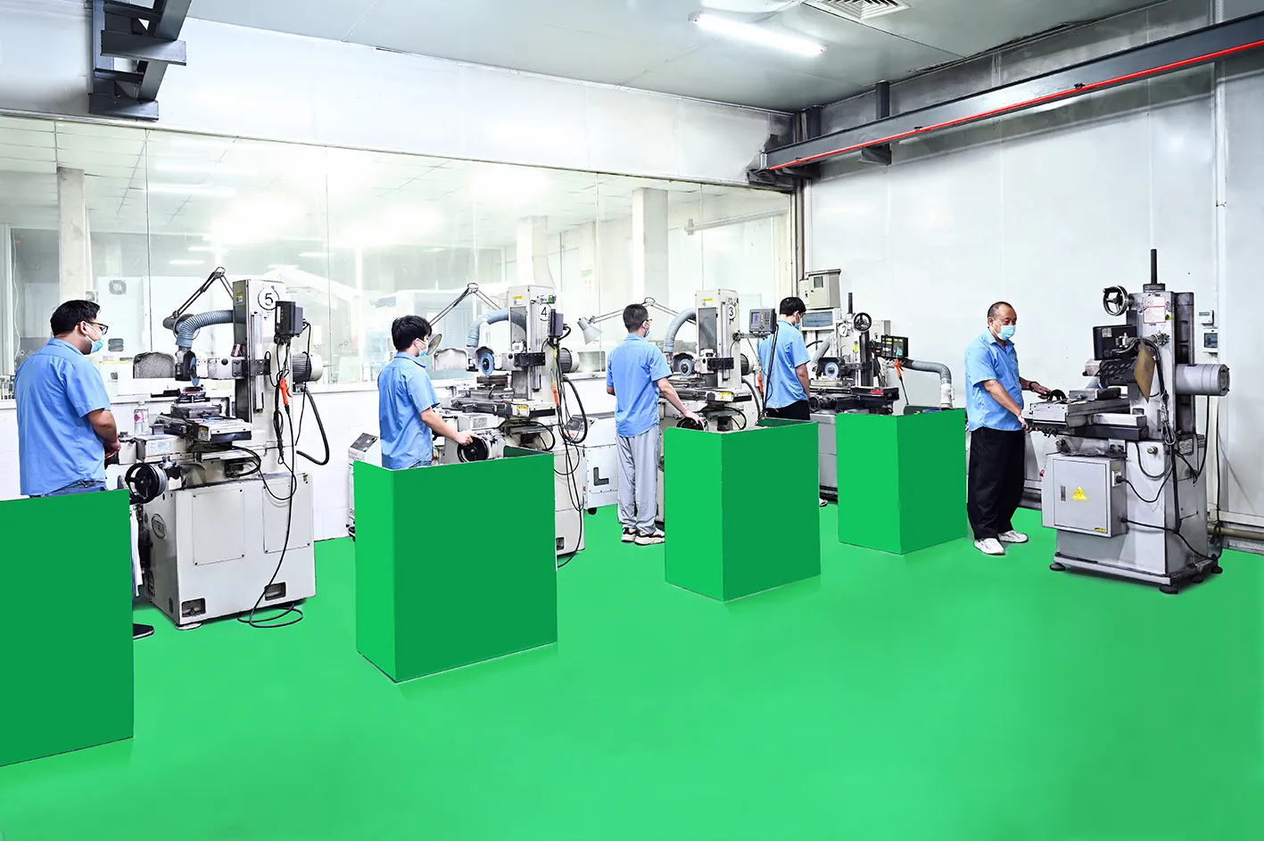
The parting line is where the mold's sharpest corners live, and where they chip sooner than anywhere else. A parting-line edge with no break is a knife-edge of steel; under clamp tonnage and the micro-movement of thermal cycling it erodes and chips, and the result is flash on the part or witness lines on the parting surface. Standard practice is to break the steel edge 0.1-0.3 mm × 45° on non-seal-off areas, protecting the edge at zero cost to the part. Where the parting line must seal against injection pressure, the edge is kept sharper and the seal-off area is ground and verified — typically on a surface grinder rather than a mill. When a chipped corner does occur, mold repair and maintenance brings the edge back with weld, re-machining, and re-polish — and the flash that escapes a worn corner is a defect pattern we cover in our mold defect troubleshooting guide.
Textured cavities change the rules for small radii. EDM texture and chemical etching — the SPI C-D grades and VDI 27-36 roughness bands — are applied to the cavity, and texture erodes fine geometry: a 0.2 mm fillet under a coarse texture simply disappears, and texture on the flanks of a sharp corner produces a feather edge that peels. On textured surfaces, specify fillets at the top of the range (≥ 0.5× wall), keep internal corners off textured faces where possible, and raise draft to 1.5-2° per side so the texture does not lock the part in the cavity.
Steel selection is the last layer. Edge retention scales with hardness: P20-class inserts at 28-34 HRC chip sooner than S136 at 48-52 HRC or H13 at 46-52 HRC. Where a parting-line corner or a thin cavity rib carries repeated thermal and mechanical load, the steel grade and hardness are part of the corner design — a trade-off we break down in P20 vs H13 vs S136.
Decision Checklist
Run this list against the drawing before the mold is quoted. Each item maps a corner situation to a specific geometry and a number, so the review is a check-off, not a discussion.
- Load-bearing corner (bending, impact, snap-fit, press-fit): fillet ≥ 0.5× wall thickness, floor 0.5 mm.
- Assembly lead-in (hole mouth, part-to-part insertion): chamfer 20-45°, typically 30-45°.
- Handled or cosmetic edge: edge break 0.2-0.5 mm × 45°.
- Wall thickness step: blend at ≤ 3:1 ratio with a fillet — never a sharp step.
- Rib and boss roots: fillet 0.25-0.5× feature thickness, low end on visible faces.
- Parting-line steel edge: break 0.1-0.3 mm × 45° outside seal-off areas.
- Radius below 0.5 mm in a machined cavity: expect EDM or custom tooling cost.
- Radius matching standard ball-mill sizes (R0.5 / R0.75 / R1.0 / R1.5 mm): one finishing pass, lowest cost.
- Draft: 0.5-1° per side minimum; 1.5-2° on textured faces; 1° per 25 mm depth on deep ribs.
- Before steel is cut: corner geometry reviewed in DFM and critical radii on the CMM report.

Two items deserve emphasis. A radius below 0.5 mm is where machining cost jumps and where the geometry starts to disappear under texture and polish — move it up or accept the EDM operation. And a chamfer on a load-bearing corner is a partial fix: it protects the edge but leaves the discontinuity, so pair it with a fillet where the part takes real load. If any item is ambiguous, our mold design DFM review settles it in 24 hours, with the corner geometry checked against the load case, the material, and the machining plan.
Frequently Asked Questions
Q1. What is the difference between a fillet and a chamfer?
A fillet is a concave radius that rounds a corner with a continuous curve; a chamfer is a straight bevel at a fixed angle, typically 45° for edge breaks and 20-45° for assembly lead-ins. Fillets spread stress and belong on load-bearing corners; chamfers guide assembly and protect edges.
Q2. What is a good fillet radius for injection molded parts?
Internal corners: ≥ 0.5 mm or 0.5× wall thickness, whichever is larger — 1.0 mm on a 2 mm wall. External corners: 0.25-0.5× wall thickness. Rib and boss roots: 0.25-0.5× their own thickness. A radius of 0.5× wall thickness drops the stress concentration factor from about 3 to 1.5-2.
Q3. When should I use a chamfer instead of a fillet?
When the job is assembly (lead-in chamfer 20-45°), edge protection (0.2-0.5 mm × 45° break), or draft (0.5-1° per side minimum). For corners that carry load, use a fillet — a chamfer's typical Kt of 2-2.5 is higher than a fillet's 1.5-2.
Q4. Does a chamfer reduce stress concentration?
Yes, compared with a sharp corner — from Kt ≈ 3 down to roughly 2-2.5 for a 45° chamfer — but a fillet of radius ≥ 0.5× wall thickness drops it further, to 1.5-2. The chamfer leaves a slope discontinuity at each end; the fillet removes it.
Q5. What chamfer angle should I use for assembly?
20-45°, with 30-45° typical for molded lead-ins. Steeper angles locate parts faster but are more sensitive to misalignment; 20° keeps insertion forces low. Edge breaks run 0.2-0.5 mm × 45°.
Q6. How do corner geometry choices affect mold cost?
Chamfers and standard-radius fillets are one finishing pass with standard tools (R0.5-R3 mm ball mills). A radius below 0.5 mm, a custom radius, or a sharp square corner adds EDM electrode work, extra tooling, and bench time — the most expensive corner on a quote.
Q7. What is an edge break?
An edge break is a small chamfer — typically 0.2-0.5 mm × 45° — applied to remove burrs and sharp edges for handling, safety, and cosmetics. On the mold side, a 0.1-0.3 mm break on parting-line steel edges protects them from chipping.
Q8. Should I put fillets on the part model or let the mold shop add them?
Put them on the part model. Fillets in the model are verified, polished, and measured; fillets added informally in the shop are uncontrolled and can vary between cavities. If you are unsure of the value, settle it in the DFM review — spec the radius in the model and let the mold shop flag conflicts before steel is cut.
The Bottom Line
Sharp corners are where molded parts crack and mold steel chips — a Kt of 3 at an unradiused corner surfaces as field failures and tool downtime. DieStrike reviews your corner geometry in a 24-hour DFM pass and verifies critical radii by CMM before the steel ships.
KEEP READING
Related Reading
How to Design Snap Fits for Injection Molded Parts
Snap fit design for injection molded parts from the mold side: cantilever strain ε = 3yt/2L², allowable strain ABS 2%,…
Read articleArticle5 Mold Cooling Channel Design Tips for Faster Cycles
Mold maker's 5 cooling channel design rules: channel-to-cavity distance 2-2.
Read articleArticle5 Shrinkage Compensation Rules for Mold Design
Shrinkage compensation decides mold accuracy. Five rules: material rates from 0.3% to 2.
Read articleArticle5 Ways to Reduce Mold Cost Without Cutting Quality
Five proven ways to reduce injection mold cost without cutting quality: DFM before quoting, right-sized cavity count,…
Read articleNEXT STEP
Ready to Start Your Mold?
Send us your element dimensions or part numbers — our team responds within 24 hours with pricing and lead time.

Written by
Ray ChanMold Buyer's Guide Author · Precision Mold Manufacturing Specialist. Ray helps global importers, distributors and OEMs source factory-direct molds and mold parts.