
How to Design Molds for Biodegradable Plastics: PLA, PHA and PBAT
Table of Contents
A PLA cutlery tool run with resin at 400 ppm moisture does not fail in the cavity. Hydrolysis cuts molecular weight in the barrel at 190 to 220 °C, and the forks then crack at ejection or in the bend test. A re-cut of a 24 cavity core set costs 5 to 10 working days plus a fresh trial day at the molder. This guide carries the mold-side numbers for PLA, PHA and PBAT: drying, mold temperature, shrinkage, gating, ejection and acid attack.
Every figure below is a typical industry value for the biodegradable family, and each one needs checking against the resin datasheet before a drawing is released.
The Snapshot
- Moisture below 250 ppm for PLA. Dry at 50 to 80 °C for 2 to 6 hours. Above 180 to 190 °C with wet resin, hydrolysis drops molecular weight shot after shot.
- Mold temperature splits the family in two. PLA runs 10 to 40 °C for clear parts and 80 to 110 °C to crystallize, which doubles the cycle from 25 to 40 s up to 45 to 90 s.
- Shrinkage spans 0.4 to 2.5 percent. Flow-to-cross-flow differentials of 0.1 to 0.3 percent let one 100 mm dimension move 0.5 to 1.0 mm between directions.
- Vents at 0.02 to 0.03 mm. Degradation gases are acidic, so vent lands corrode and need a written wipe schedule on the tool file.
Why Biodegradable Resins Are a Different Tool Problem
A standard mold assumes the resin arrives at the press chemically stable. The biodegradable family breaks that assumption on purpose. PLA is a polyester engineered to hydrolyze, and heat plus water start the reaction. Tool design controls both levers as far as the mold can, then protects the steel from the acid the process makes.
The barrel behaves like a reactor. PLA melt sits at 190 to 220 °C, and resin above 250 to 500 ppm moisture begins chain scission past 180 to 190 °C. Every minute of residence destroys molecular weight. Color drifts, the part turns brittle, and no dimension on the CMM report changes, so the failure hides from a dimensional-only trial.
Each resin pulls the tool a different way. PHA loses properties above 160 to 175 °C, so its hot runner is a hazard. PBAT stretches like rubber and grabs a chrome-plated face. Starch blends keep absorbing water after molding. The table carries the family numbers used through the rest of this guide.
| Resin | Drying target | Mold temperature | Shrinkage | Tool-side consequence |
|---|---|---|---|---|
| PLA | under 250 ppm, 50 to 80 °C for 2 to 6 h | 10 to 40 °C amorphous, 80 to 110 °C crystallized | 0.4 to 0.7 percent, 0.6 to 1.0 crystallized | Tg at 55 to 65 °C, sticks and jams hot, notch-sensitive at ejection |
| PHA | under 300 ppm, 40 to 60 °C for 4 to 12 h | 20 to 60 °C | 0.8 to 1.5 percent | property loss above 160 to 175 °C, short hot-runner residence allowed |
| PBAT | under 200 ppm, 60 to 80 °C for 3 to 6 h | 25 to 50 °C | 1.5 to 2.5 percent | elastic grab on chrome, big shrinkage band on deep parts |
| Starch blends | moisture-balanced, 50 to 70 °C before molding | 30 to 60 °C | 0.4 to 0.8 percent plus moisture drift | dimensions move with humidity for days after the shot |
← swipe to scroll →
Table note: drying, temperature and shrinkage bands are typical published values for packaging-grade resins. Confirm each number against the supplier datasheet and lot data before cavity steel is cut.
Degradation gases from PLA and PBAT are mildly acidic. They plate onto cold vent lands and etch unprotected steel over thousands of shots. A tool designed for PP tolerates that film for a year. The same tool on PLA shows vent corrosion and dull spots inside a quarter of that time.
Drying Windows and the Moisture Line
The mold cannot dry resin, so the tool has to be designed for a dry input and checked against it. PLA needs 50 to 80 °C for 2 to 6 hours down to under 250 ppm. PHA needs a gentler 40 to 60 °C for 4 to 12 hours to under 300 ppm, because its softening point is low. PBAT needs 60 to 80 °C for 3 to 6 hours to under 200 ppm, and it reabsorbs water fast once the hopper empties.
The dryer air has to reach a dew point of minus 35 to minus 40 °C, or the resin never gives up the last 100 ppm. A desiccant bed past its regeneration cycle holds at 400 to 500 ppm no matter how long the dwell runs. That is a dryer fault that reads as a mold fault, so the trial record logs the dew point next to the shot count.
Wet resin shows two symptoms and one hidden cost. Splay and silver streaks are the visible ones. The hidden one is falling molecular weight, and it moves no dimension you can measure at the tool. A molder who sees splay plus a brittleness creep has a drying problem, not a gate problem. The full hopper setup sits in the resin drying guide.
The tool consequence: keep the shot size honest. A 60 g part on a 300 g machine spends most of its melt time in the barrel, degrading. Cavitate so the shot runs 30 to 70 percent of machine capacity and put that number on the drawing.
Mold Temperature and Crystallinity
PLA has a glass transition at 55 to 65 °C, and that one line decides two different molds for two different parts. Below it the part stays amorphous and clear. Above it, held long enough, PLA crystallizes, turns opaque and gains heat resistance to 90 to 110 °C plus measurable stiffness. The molder picks the mold temperature; the tool designer builds a mold that holds it evenly.
For clear cutlery, cups and clamshells the mold runs 10 to 40 °C, with chilled water at 8 to 14 °C and a delta under 5 °C across the cavity. For a hot-fill lid the mold runs 80 to 110 °C, and the base carries oil or pressurized-water temperature control, not open chilled circuits. That decision belongs on the quote before the base is drilled, because a 110 °C layout cannot be retrofitted into a base cut for 15 °C water without a re-drill day.
The cost of crystallinity is time. The part must be held above Tg for seconds, and that hold doubles the cycle: a 25 to 40 s amorphous part becomes a 45 to 90 s crystallized part at the same wall. A quote that assumes a drop-in cycle on crystallizing PLA underprices the program by 15 to 40 percent, so write the expected cycle band on the drawing.
A hot mold is also a sticky mold. At 80 to 110 °C the part sits above its own Tg when the cavity opens, and any undercut, polish scratch or soft steel will pull it. PHA and PBAT run cooler, 20 to 60 °C and 25 to 50 °C, and PHA adds a hard melt ceiling: usable window about 15 to 25 °C wide below the 160 to 175 °C degradation point, against roughly 40 °C for PLA.
Shrinkage and Tolerance Bands
Shrinkage sets the cavity dimension, and this family spreads wider than the polyolefins most mold bases are drawn around. Amorphous PLA at a cold mold shrinks 0.4 to 0.7 percent, crystallized PLA 0.6 to 1.0, PHA 0.8 to 1.5, PBAT 1.5 to 2.5, which is closer to a soft PE than to a stiff engineering resin. Starch blends shrink 0.4 to 0.8 percent and then drift with moisture after ejection.
The gate-direction differential is the number that kills fits. Flow and cross-flow shrinkage separate by 0.1 to 0.3 percent, so a 100 mm dimension can sit 0.5 to 1.0 mm apart between the two directions depending on where the gate puts the flow front. A lid that snaps onto a bowl in the CAD can miss by that margin at trial. Orient the critical dimension along one flow direction, then cut steel for that direction.

Build the compensation into the cavity, not into the process. Pack and hold move PLA dimensions less than they move PP, because the melt solidifies fast under Tg. A 100 °C mold on crystallizing PLA needs its own shrinkage value, different from the same part at 20 °C, so the datasheet number must match the planned mold temperature. On starch blends, measure at 24 to 48 hours after molding at 23 °C and 50 percent relative humidity: a hot dimension can move 0.2 to 0.5 mm per 100 mm while the blend rebalances moisture. Write that condition into the acceptance check.
Gating and Jetting Discipline
PLA at 190 to 220 °C is thin, fast and low in viscosity. A gate sized like a PP gate will jet: the melt snakes across the cavity, freezes against the wall and welds as a visible line with gas trapped under it. A jetting guard means a gate land of 0.5 to 0.8 mm with immediate expansion, or an entry along the wall instead of across open space.
Keep the runner volume under 1.2 times the shot. Runner material sitting hot is runner material degrading, and a degraded slug becomes a dark speck or gel in the next cavity. On a 24 cavity cutlery tool, that ratio decides whether the runner weighs more than the parts.
Hot runners need resin-specific temperature discipline. A valve gate tip for PLA holds 90 to 110 °C, warm enough to keep the seal face clean without cooking the melt. For PHA, keep every zone under 160 to 175 °C, hold residence short and never let a manifold exceed 180 °C, even in a start-up overshoot; melt in a manifold alarming at 180 °C is already damaged stock.
Gate type also drives appearance on transparent PLA. Pinpoint gates leave a stress-whitening ring on a notch-sensitive part; submarine and film gates spread the entry. Vestige rules on thin bioplastic walls start at a 0.5 mm land, because a smaller vestige pulls out ragged.
Ejection and the Brittleness Problem
Crystallized PLA behaves like a notched ceramic at room temperature, and a scratch is a crack starter. An ejector pin landing on a cosmetic face leaves a white mark first and a hairline crack later, and the crack propagates in the bend test, not the CMM report. Ejection design here is damage avoidance specified on the drawing.
Land ejectors on ribs and bosses at 0.4 to 0.8 mm pin contact diameter, never on a cosmetic face and never on a 0.6 to 1.2 mm free wall. Draft runs 2 to 3 degrees minimum plus 1 degree per 25 mm of core depth, because hot PLA above its Tg galls on a 1.5 degree core, and the packer pressure that frees a stuck part cracks the next shot.
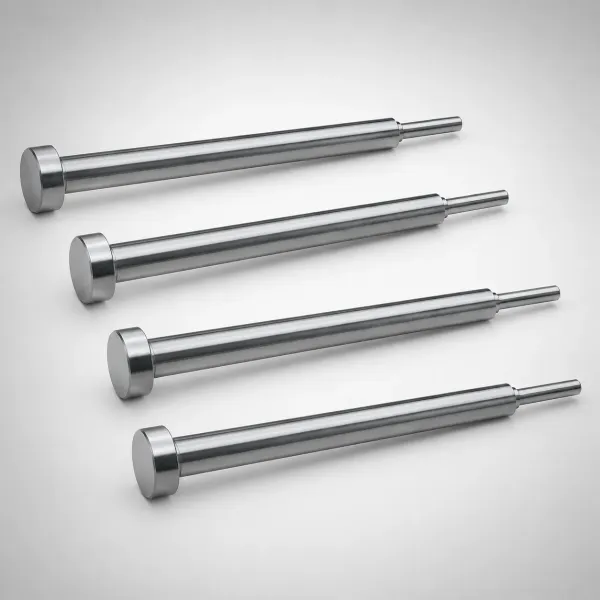
Eject the part at 5 to 10 °C above the glass transition, roughly a 60 to 75 °C part. Below Tg the part is glass and crazes under the pin; far above it the part is rubber and drags across the parting line. On a hot-mold crystallizing cycle that ejection temperature, not the clock, sets the hold time.
For deep thin-wall cups and trays use stripper sleeves or a plate instead of pins. A 0.8 mm wall cup with a 40 mm draw wraps the core in friction and lifts at 150 to 300 N, and point loads oil-can the wall; a sleeve spreads the force across the full rim, as laid out in the ejector system design guide. Finish matters at ejection more than appearance: a mirror face grips PLA through micro-vacuum and cold welding on chrome, while an SPI-27 to 45 texture at 15 to 40 µm Ra breaks away and hides flow lines.
Venting and Acid Corrosion
Volatiles from a degrading polyester are acidic, and they condense on the cold vent land. Over 50,000 to 200,000 shots that film etches the steel: the vent channel widens, the land grows ragged, and burn marks return on a tool that vented fine when new. Vent design here is metal selection plus maintenance, not just depth.
Run vents at 0.02 to 0.03 mm on the last-fill corner, shallower than the 0.03 to 0.05 mm typical on PP, because thin fast PLA flashes into anything it can enter. Deeper vents flash, and the flash edge plates with acid-degraded film and leaves a burr on every part. Put vent steel in a replaceable insert at last fill, so the corroded land is a 1 to 2 day insert swap instead of a cavity weld.
Wipe the vents every 2,000 to 5,000 shots on a PLA or PBAT run and log it: copper or brass brush, neutral cleaner, no acid bath, no grinding stone on the land. The schedule belongs in the tool file next to the shut-off dimensions. For 0.5 to 0.8 mm thin walls, vacuum-assisted venting pulls acid-laden gas out before it condenses and keeps the vent depth at the shallow end of the band.
Tool Steel and Surface Finish
Acid, moisture and a 110 °C mold make bioplastic duty corrosive, and P20 pre-hardened is the wrong default for a production tool. 420 stainless at HRC 48 to 52, or 1.2316 (S136), is the sensible cavity steel for PLA and PBAT programs, for the same reason it is the default on PVC and flame-retardant work: chromium resists the acid film that condenses on vents and shut-offs. We cut those inserts to plus or minus 0.005 mm under an IATF 16949 quality system, with plus or minus 0.002 mm on the EDM and jig-grinding passes that form vent lands and gate pockets.
Coatings need a resin-specific decision. Hard chrome at 25 to 40 µm protects P20 bodies against abrasion and works well on PLA cutlery steel. PBAT is the exception: its elastic grab holds a chrome face and can rip the coating at a land over tens of thousands of strokes, so PBAT cavities go stainless and textured instead.
Texture also decides what the eye sees after the press. Hydrolysis haze, gate blush and flow lines read loudly on an SPI-1 to 3 gloss face, and a fine SPI-27 to 45 texture hides them. Two downstream rules follow. In-mold label film bonds to PP and PE by partially melting into the surface; a PLA part at a 10 to 40 °C mold never gets hot enough to wet the label, so IML on PLA needs a mechanical key or adhesive step decided before the cavity is cut. And no mold spray or release agent belongs on a face whose parts will be printed, glued or labeled, because silicone transfer ruins ink adhesion on every part in the carton.
Part Families and Cavity Count
The volume in this family sits in thin, light, high-count parts. Cutlery and clear cups run 3 to 8 g at a 0.6 to 1.2 mm wall on 12 to 24 cavities, a balance problem before a filling problem: at 1,200 to 4,800 mm² total projected area the clamp needs 40 to 120 tons, and all cavities should fill within 1 to 2 seconds of one another or the parts sort into two quality populations. Blister and clamshell packs run 0.5 to 1.0 mm walls where vent depth and vacuum assist decide whether the last corner fills. Closures run 2 to 10 g with a thread that must hold plus or minus 0.1 mm across the 0.4 to 0.7 percent shrink band.
Agricultural film tooling and plant pots add the PBAT and starch numbers: a 1.5 to 2.5 percent shrink on a 150 mm pot rim is a 2 to 4 mm cavity oversize, and the acceptance gauge reads at 24 to 48 hours, not at T1. Lead times follow normal multi-cavity rules: a 12 to 24 cavity cutlery set from a print and a validated resin grade lands in 2 to 5 weeks at a shop running 120+ machines, with standard components such as ejector sleeves, core pins and return springs shipping in 3 to 7 days.
Verify the family before committing steel. Run a moisture spec on incoming resin: a PLA lot at 320 ppm in the bag is a receiving-inspection number, not a molding parameter. The molder you buy from owns the barrel; the tool owner owns the cavity, the vents and the acceptance record, and all three should carry the same numbers.
Family Molds and Resin Switching
One mold, one drop-in resin, no penalty: the marketing version of bioplastic switching does not survive a shop floor. PLA and PP in one tool is a cleaning war. The two melts disagree by 60 to 80 °C on melt temperature, 30 to 60 °C on mold temperature, and on every shut-off cut for the shrink of one of them. Plan 8 to 10 full-volume purge shots on screw and check-ring changeover, a 15 to 30 minute temperature soak each way, and a 15 to 40 percent cycle penalty versus the single-resin tool until the process is re-centered.
PHA deserves dedicated metal. A manifold that once ran PA6 at 280 °C holds a charred film that PHA picks up as black specks within a few hundred shots. If the program calls for PLA and PHA, run a dedicated barrel and hot-runner set, or run PHA cold-runner; the color and gel logic matches the regrind reasoning in the recycled plastics mold guide.
Sticking is the shared failure across the family, and it is a tool condition, not a bad day. Release-agent-free operation, polished shallow-surface cores, 2 to 3 degrees of draft and vents that breathe keep PLA off the steel; the ladder from first drag to torn part is mapped in the sticking prevention guide.
Bioplastic Mold Design Checklist
Run this list against the tool drawing before a bioplastic mold is released to the shop. Each line names a number the reviewer reads off the print, not off the press.
- Resin and drying spec. Grade, moisture limit (PLA under 250 ppm, PHA under 300 ppm, PBAT under 200 ppm) and dryer dew point minus 35 to minus 40 °C stated on the RFQ.
- Mold temperature decision. 10 to 40 °C amorphous or 80 to 110 °C crystallizing for PLA, 20 to 60 °C PHA, 25 to 50 °C PBAT, with matching circuits in the base.
- Shrinkage map. Flow and cross-flow values separated by the 0.1 to 0.3 percent differential, critical dimensions oriented to one direction.
- Gate design. 0.5 to 0.8 mm land against jetting, runner volume under 1.2 times shot, valve gate tip at 90 to 110 °C for PLA, hot-runner zones capped at 160 to 175 °C for PHA.
- Ejection plan. Pin lands 0.4 to 0.8 mm on ribs and bosses only, 2 to 3 degrees draft plus 1 degree per 25 mm depth, stripper sleeves on deep thin cups, ejection at 5 to 10 °C above Tg.
- Vent and corrosion file. 0.02 to 0.03 mm vents in replaceable inserts, wiped every 2,000 to 5,000 shots, 420 or S136 cavity steel on production programs.
- Acceptance evidence. Dimensions at 23 °C and 50 percent relative humidity after 24 to 48 hours, bend test on parts from a logged-dryness run, cavity count and cycle band on the drawing.
The checklist doubles as the tool file. A mold carrying its drying spec, temperature map, shrinkage values and vent schedule runs the same in month twelve as on trial day.
The Bottom Line
Biodegradable mold design is four numbers held at once. Keep the input dry: PLA under 250 ppm, PHA under 300 ppm, PBAT under 200 ppm at a minus 35 to minus 40 °C dew point. Keep the mold honest: 10 to 40 °C for clear amorphous PLA, 80 to 110 °C for crystallized parts at a doubled 45 to 90 second cycle. Cut steel for the shrink band: 0.4 to 0.7 percent amorphous PLA, up to 1.0 crystallized, 0.8 to 1.5 for PHA, 1.5 to 2.5 for PBAT, with the 0.1 to 0.3 percent differential mapped first. Protect the metal: 0.02 to 0.03 mm vents in replaceable inserts, wiped every 2,000 to 5,000 shots, on 420 or S136 faces.
DieStrike makes the mold, not the part. We tool it to plus or minus 0.005 mm with plus or minus 0.002 mm on EDM and jig grinding, HRC 62 maximum heat treatment, 120+ machines under an IATF 16949 quality system, standard components in 3 to 7 days and tool lead times of 2 to 5 weeks, with tier-1 references that include TE, Amphenol, Luxshare and Dongshan. Send the part print, resin grade, drying spec and target mold temperature through mold design and DFM, and the cavity starts from the material's numbers rather than a PP guess.
KEEP READING
Related Reading
5 Shrinkage Compensation Rules
How gate-direction shrinkage differentials get built into cavity steel before the first cut.
Read articleArticleHow to Set Up Resin Drying
Desiccant dew point, hopper temperature and dwell windows for hygroscopic resins.
Read articleArticleHow to Prevent Burn Marks
Vent depth, last-fill layout and vacuum assist for trapped-gas defects.
Read articleServiceMold Design and DFM
IATF 16949 tool design reviews with shrinkage mapping, vent layout and 2 to 5 week lead times.
Read articleNEXT STEP
Ready to Start Your Mold?
Send us your element dimensions or part numbers — our team responds within 24 hours. Pricing and lead time come with the answer.

Written by
Ray ChanExport Brand Manager at DieStrike. Ray helps global importers, distributors and OEMs source factory-direct molds and mold parts.