
How to Fix Dimensional Instability: Shrinkage and Post-Mold Drift
Table of Contents
A connector lot passed final inspection on Monday at 4.82 mm pin spacing. On Wednesday the same mold, same material brand, same machine produced 4.96 mm on the same feature. The print tolerance was ±0.05 mm around a 4.90 mm nominal, so both lots sat inside the box, but the 0.14 mm drift between them pushed the Wednesday parts toward the upper limit and cut the process capability index to Cpk 0.8. The customer audit flagged the lot, and 12,000 connectors went to 100% sorting at $0.08 per piece.
That is dimensional instability, and it is a different failure than a single out-of-tolerance part. One bad part is a defect. A population that wanders is a process problem, and it hides inside tolerance until a shift change, a new resin lot, or a summer coolant temperature exposes it. Unstable molds produce scrap in slow motion: capability erodes, sampling plans tighten, and customers lose trust before a single part formally fails.
This guide stays on the mold side of dimensional drift. Single-defect fixes like sink marks and thin-wall warpage have their own articles, and we link them where the mechanisms overlap. Here the target is batch-to-batch and shot-to-shot variation: cooling imbalance, pack pressure loss, ejection stress, resin moisture and lot spread, and the slow post-mold movement of crystalline materials. Values are typical published figures for injection molding practice. Confirm them against your resin datasheet and your own capability data.
The Snapshot
- 1. Instability is spread, not position. Track standard deviation across lots, not just max-min against print. A capable process holds Cpk ≥ 1.33, which means total spread inside half the tolerance band with 3-sigma margin.
- 2. Measurement is the first suspect. Condition parts at 23 ± 2 °C and 50 ± 5% RH for 24-48 h before CMM work. Crystalline resins keep moving for days, and a 5 °C part temperature error alone shifts a 100 mm glass-filled feature by about 0.025 mm.
- 3. Cooling imbalance is the top mold-side driver. Hold cavity-to-cavity surface spread under 5 °C, coolant circuits turbulent at Reynolds number above 10,000, and circuit delta-T inside 2-4 °C.
- 4. Gate freeze timing controls pack transfer. A gate that solidifies before pack ends starves the cavity and makes density vary shot to shot. Gate freeze happens in roughly 0.5-3 s for 0.5-2.0 mm gate sections, and pack time must exceed it.
- 5. Crystalline resins shrink after ejection. Post-crystallization adds 0.1-0.5% dimensional change over days to weeks at service temperature. Annealing (for example 120-140 °C for 2-4 h for POM parts, typical) stabilizes dimensions before assembly or inspection.
Instability vs Out of Tolerance: Two Different Failures
An out-of-tolerance part fails a limit. An unstable process fails a distribution. The distinction changes everything downstream, because the fixes are different. A part 0.08 mm over nominal on one critical pin gets reworked or scrapped. A process whose mean walks 0.1 mm across a week gets a mold correction, because every part carries the same latent risk.
Use three numbers to separate the two. First, the mean: is the population centered on nominal, or shifted? Second, the spread: what is the standard deviation across the lot, and across lots? Third, the drift: plot lot means in time order and look for a trend. A shifted mean with tight spread is a shrinkage compensation error, usually fixed by a single mold dimension change. A wide spread with stable mean points at inconsistent filling, packing, or cooling. A walking mean points at something changing systematically: coolant temperature with the seasons, a wearing gate, or a material lot switch.
Capability math makes this concrete. For a ±0.05 mm tolerance, Cpk 1.33 requires 3-sigma spread under about 0.037 mm, so total 6-sigma variation must fit inside roughly 0.075 mm of the 0.10 mm band. If your lot-to-lot spread alone eats 0.10 mm, no mean shift even needs to happen for parts to fail. Read the numbers the right way first: our guide on how to read a CMM report covers datum frames, true position reporting, and the Cp vs Cpk difference that buyers need before arguing about a mold.

One trap belongs here, not later. Gauge repeatability can masquerade as process instability. A CMM program with poorly fixtured parts, or a hand gauge used at inconsistent temperature, injects its own variation. Before condemning the mold, run a gauge study: same operator, same part, ten measurements. Measurement variation should stay under 10% of tolerance (gauge R&R below 10% is the typical automotive acceptance line). If the gauge itself wanders 0.03 mm, half your "instability" is the inspection room.
Measure Correctly First: The Conditioning Protocol
Plastic parts are not steel blocks. They keep shrinking, relaxing, and swelling with moisture for hours to weeks after ejection, and they expand with temperature far more than the fixtures measuring them. A part measured warm off the press, then again cold the next day, can differ by more than the entire tolerance band without anything wrong in the mold.
Follow a conditioning protocol before any capability decision. The typical industry practice: hold parts at 23 ± 2 °C and 50 ± 5% relative humidity for 24-48 hours, per the standard laboratory atmosphere used in ISO and ASTM test methods. Measure at 20 °C reference temperature, the ISO default for dimensional metrology. For semicrystalline resins like POM, PA and PBT, extend conditioning or measure at defined intervals, because post-crystallization keeps moving dimensions for days. Our shrinkage compensation guide covers the mold-side math in 5 shrinkage compensation rules.
The thermal expansion numbers show why this matters. Mold steel expands at about 11-12 µm/m·K. A 30% glass-filled polyamide part expands at roughly 20-30 µm/m·K in the flow direction, and unfilled resins run 50-90 µm/m·K. Take a 100 mm unfilled POM feature: a 5 °C temperature difference between two measurement sessions produces about 5 × 70 µm/m·K × 0.1 m = 0.035 mm of apparent dimensional change. That is 70% of a ±0.05 mm tolerance consumed by measurement temperature alone. Hygroscopic resins add another axis: a PA66 part that reabsorbs moisture from 0.2% to equilibrium near 2.5-3.5% grows measurably, sometimes 0.5-1% linear, which dwarfs most tolerances.
Practical protocol for an instability investigation: sample parts at fixed intervals from three consecutive lots, condition them identically, measure the same features on the same CMM with the same fixture, and record lot number, resin lot number, and time since molding with every data point. Data without resin lot traceability cannot separate material variation from process variation, which is the whole point of the exercise.
Mold-Side Cause 1: Cooling Imbalance and Cavity Temperature Spread
Shrinkage is a function of cooling history. Two cavities in the same mold that run at different temperatures produce parts with different crystallinity, different frozen-in stress, and different shrinkage, even when every machine setting is identical. Across a production day, coolant temperature itself drifts with ambient conditions and chiller load, and the whole population walks with it.
Set the target first: cavity-to-cavity surface temperature spread under 5 °C, verified with an infrared thermometer or surface probes on the open mold at steady state (typically after 20-30 minutes of cycling). Circuit-level targets: turbulent flow with Reynolds number above 10,000, which for a 10 mm channel in 20 °C water means roughly 5-10 L/min per circuit, and a coolant temperature rise of 2-4 °C from circuit inlet to outlet. Laminar flow below Re 4,000 cuts heat transfer dramatically and lets local hot spots persist.
The common mold-side failures that create imbalance: series-connected circuits where the last cavity sees water already warmed 3-5 °C by the first; long unsupported channels in thick cores where convection stalls; a hot side created by the sprue and runner mass with no dedicated cooling; and inserts of low-conductivity steel where heat accumulates. Beryllium-copper inserts at roughly 100-120 W/m·K (against about 30 W/m·K for P20 tool steel) are the standard fix for hot spots under thick sections or deep cores.

The seasonal signature is diagnostic. If dimensions drift with weather, the coolant loop is the suspect: an unchilled tower-water supply can swing 10-15 °C between winter and summer, and mold surface temperature follows it. A process chiller holding ±1 °C removes that variable completely. Track coolant inlet temperature as a logged process parameter, not an assumption. When one cavity consistently produces larger parts than its neighbors by 0.03-0.05 mm, and the pattern repeats shot after shot, the fix is cooling geometry, not holding pressure: rebalance circuits, add baffles or bubblers in dead zones, or convert the problem core to a high-conductivity insert.
Mold-Side Cause 2: Pack Pressure Loss and Early Gate Freeze
Pack pressure is what sets part density, and density is what sets shrinkage. If pack pressure reaches the cavity consistently, shrinkage is repeatable even when it is large. If the gate freezes before pack ends, or the packing profile shifts between shots, the cavity seals at a different density every time and dimensions scatter. This is the second most common mold-side cause of instability, and it produces a signature: part weight varies shot to shot by more than about 1-2%.
Gate freeze time is short. A 0.5-1.0 mm edge gate section solidifies in roughly 0.5-1.5 s, a 1.5-2.0 mm gate in about 2-3 s, and a hot runner valve gate stays open as long as the nozzle holds temperature. Pack time must exceed gate freeze time by a margin (typically 0.5-1.0 s), or the tail end of the pack profile does nothing. The verification is a seal study: run increasing pack times, weigh parts, and find the point where weight stops rising. That flat plateau is true gate seal, and it is a mold fingerprint that changes if the gate geometry or steel temperature changes.
Mold-side causes of inconsistent pack transfer: an undersized gate that freezes before the cavity is dense; a runner too small to carry pack pressure (pressure loss along a long cold runner can exceed 30-50%); a hot runner thermocouple drifting 5-10 °C, which changes gate viscosity shift to shift; and venting so weak at the end of fill that the cavity pressurizes against trapped air, then density varies with air volume. A worn or damaged gate is sneakier: erosion widens the gate over hundreds of thousands of shots, freeze time lengthens, and parts slowly grow denser. If a mold's dimensions have drifted progressively since commissioning, measure the gate against the drawing.
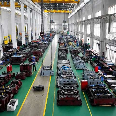
The mold modification options, in escalating order: polish or re-cut the gate land to the designed depth; enlarge the gate section by 10-20% where fill and cosmetics allow; shorten or enlarge cold runners to cut pressure loss; convert a problem cavity to a valve gate where the tool has hot runner capacity; and add or deepen vents (typical depths: PP/PE 0.02-0.04 mm, ABS 0.03 mm, PC 0.02-0.04 mm, POM 0.01-0.02 mm) at the last-fill point so air stops competing with pack pressure. Every one of these changes part density, so re-run the seal study and a capability check after any gate or vent modification.
Mold-Side Cause 3: Ejection Distortion and Residual Stress
A part leaves the mold hot, soft, and full of frozen-in stress. How it is pushed out, and what happens in the minutes after, writes dimensions that measurement will see hours later. Ejection distortion is the classic cause of instability that looks like a shrinkage problem but responds to none of the shrinkage fixes.
Three mold-side mechanisms matter. First, uneven ejection force: pins concentrated on one side of a deep box let the far wall drag, and the part twists as it cools in that twisted state. The design targets live in our ejector system guide: pin tip area near 1-3% of projected area, spacing on an 8-15 mm grid, and pin-to-bore clearance of 0.01-0.02 mm so pins neither bind nor flash. Second, premature ejection: if the core-side skin has not stiffened enough, the part deforms under its own weight plus pin pressure. Cycle time cut by even 0.5-1.0 s below the cooling threshold produces exactly this failure, and the distortion is not uniform, which is why dimensions scatter. Third, stress relaxation: parts frozen in with high residual stress from aggressive pack or cold cavities slowly relax over days, moving dimensions after they passed inspection. Annealing a sample (for example 2 h at a temperature 10-20 °C below the resin's heat deflection point, typical practice) reveals the total latent movement in a few hours instead of weeks.
Diagnostic pattern: if the out-of-flatness or bend direction is consistent relative to the mold (always toward cavity 3, always bowing away from the gate), suspect cooling asymmetry and ejection timing. If the direction is random shot to shot, suspect handling and cooling fixtures after ejection. Parts that land in a bin and cool under each other for an hour are being "fixtured" by the bin. For anything with a Cpk requirement, parts should cool on a flat surface or in a dedicated rack, and this is worth writing into the work instruction even though it is not a mold fix.
Material-Side Causes: Moisture, Regrind and Lot Shrinkage Spread
Not all instability lives in the steel. Resin is the other half of the system, and three material-side variables routinely eat tolerance bands: moisture, regrind ratio, and lot-to-lot shrinkage spread.
Moisture. Hydrolysis-prone resins (PET, PBT, PA, PC, LCP) must be dried to low moisture before molding, typically under 0.02% and for some grades under 0.005%. Wet resin degrades during melt, losing molecular weight, and the degraded material shrinks and flows differently. A dryer running at setpoint but with a desiccant past its life produces resin at 0.05-0.10% moisture that molds fine visually and drifts dimensionally. Verify with a moisture analyzer at the hopper, not the dryer display. Dew point of the drying air should read about -40 °C or lower for these materials, and drying time is typically 3-5 h for PA at 80-90 °C, 4-6 h for PET/PBT at 120-170 °C depending on grade and bed depth.
Regrind. Regrind changes shrinkage because it changes molecular weight distribution, crystallinity history, and (in filled grades) fiber length. Fiber length takes the biggest hit: each reprocessing pass shortens glass fibers, and shorter fibers shrink more in the flow direction. Running 0% regrind on Monday and 20% on Wednesday is a dimensional change disguised as process drift. If the program permits regrind, fix the ratio (commonly capped at 10-25% depending on resin and application) and enforce it in the work instruction. Our material guide on PBT for connector molding covers drying and regrind practice for one of the most common filled grades.
Lot spread. Resin suppliers publish typical shrinkage values with a range. A 30% glass-filled PBT might spec 0.4-0.6% mold shrinkage. Across resin lots from different production campaigns, actual shrinkage wanders inside that band, and a 0.2% difference on a 50 mm dimension is 0.10 mm, twice a ±0.05 mm tolerance. Mitigations: buy to a tighter supplier spec where the application needs it, qualify each incoming lot with a molded shrinkage plaque (a standard 100 mm flow/cross-flow test mold), and keep lot traceability so a drifting population can be matched to its resin lots. If parts move when the lot changes and return when it changes back, no mold modification will fix it; only lot qualification and process window adjustment will.
Post-Mold Movement: Post-Crystallization, Annealing and Time
Crystalline resins (POM, PA, PBT, PET, PP, PPS) leave the mold only partially crystallized. Crystallization continues at ambient or service temperature for days to weeks, and crystals are denser than amorphous regions, so the part keeps shrinking. This is post-mold movement, and it is the reason a POM gear measured at 24 h differs from the same gear measured at 30 days, typically by another 0.1-0.3% linear change.
Two levers control it. The first is mold temperature: hotter cavities crystallize more of the material in-mold, leaving less to do later. For POM, a mold at 80-105 °C produces far more dimensionally stable parts than one at 40 °C, at the cost of longer cooling time. The second is annealing: heat parts in an oven (typical for POM: 120-140 °C for 2-4 h; for PA: conditioning in a hot water bath at 70-90 °C to accelerate moisture equilibrium) to finish the structural relaxation on purpose, then let them return to measurement conditions. Annealing must happen before final inspection and assembly, never after.
Moisture-driven movement is the mirror image for polyamides. Dry-as-molded PA66 parts absorb water to equilibrium (about 2.5-3.5% by weight at 50% RH, higher in humid climates) and grow, often 0.5-1% linear. A PA part measured bone-dry and the same part at equilibrium differ by more than most tolerances allow. Decide which state the print dimension refers to, write it into the inspection instruction, and condition every sample to that state. Unstable populations in hygroscopic resins are very often an uncontrolled measurement state, not an unstable mold.
Mold Modification Levers: What to Cut, Weld and Re-Flow
When the diagnosis points at the steel, the question becomes what a mold shop can actually change, at what risk, and in what order. Mold modifications for dimensional stability fall into three families: additive (weld and re-machine), subtractive (cut away), and thermal (change what the steel does with heat). The order of operations matters, because a subtractive change cannot be undone cheaply.
| Symptom Pattern | Likely Root Cause | Mold-Side Fix | Reversibility |
|---|---|---|---|
| One cavity always bigger, pattern repeats | Cooling imbalance or gate size difference in that cavity | Verify circuit delta-T, add baffle/BeCu insert, equalize gate land | High (thermal) to medium (gate weld) |
| All parts drift with weather or shift | Coolant supply not temperature-controlled | Chiller at ±1 °C, log inlet temp; no steel change | Full |
| Part weight varies shot to shot over 1-2% | Gate freezing before pack ends, weak vents | Seal study, extend pack, deepen vents to resin spec | Medium (vent cutting is subtractive) |
| Mean walked since mold commissioning | Gate erosion, core wear | Measure gate vs drawing, weld-and-recut or insert replacement | Medium (weld additive, then machine) |
| Dimensions change with resin lot only | Lot shrinkage spread exceeds window | No steel fix; lot qualification plaques, tighter supplier spec | N/A |
| Parts move after passing inspection | Post-crystallization, moisture uptake, stress relaxation | Raise mold temp for crystallinity, add anneal/condition step to routing | Full |
← swipe to scroll →
Table note: Typical industry decision patterns for mold-side dimensional corrections. Confirm against your own capability data before cutting steel.
Steel-changed dimensions deserve their own rules. If a feature runs consistently small by 0.03 mm because shrinkage came in above the design value, the correction is to cut that cavity dimension larger by the measured offset, one edit at a time, re-verified with a 30-piece capability run. Never stack three corrections into one edit: if the result overshoots, you no longer know which mechanism you misjudged. Weld repairs on hardened HRC 62 cavities need matched filler and post-weld tempering discipline, and the full workflow lives in our guide to repairing a damaged mold. For thin-wall features where warpage drives the instability more than shrinkage does, the mold-side levers (cooling differential under 5 °C, wall transitions, gate position) are covered in how to avoid warpage in thin-wall molds.

Lock the Window: SPC and Process Qualification
A corrected mold is only stable if the window around it stays controlled. The last phase of any instability fix is qualification: prove the process holds before production, then watch it during production.
Qualification practice, typical for automotive-adjacent programs: run a capability study of at least 30 consecutive parts (many programs ask 50-125 for Ppk/Cpk sign-off) at the frozen settings, conditioned and measured per protocol. Acceptance commonly sits at Cpk ≥ 1.33 for critical features during production, with Ppk ≥ 1.67 for initial process studies. Document everything that fixes the window: resin supplier and grade, dryer settings and verified moisture, coolant inlet temperature and flow, pack profile with seal time, cooling time floor, ejection settings, and the conditioning-and-measurement instruction. This is the process sheet that makes the next shift, and the next year, produce the same part.
In production, statistical process control catches drift before it becomes a bad lot. Chart the critical feature every lot, or every shift for high-risk programs. Reaction rules matter more than chart type: a single point outside control limits, seven consecutive points trending one direction, or any point beyond 2 sigma triggers a stop-and-check against the process sheet. Because dimensional drift in molds usually comes with a physical cause (dryer desiccant dying, gate eroding, chiller fouling), the check is a short list, not an investigation, provided the process sheet exists.
Two long-lead warnings round this out. First, cooling circuits foul: scale of 0.5 mm roughly halves heat transfer, so a mold that qualified in year one can drift in year three without any change in settings. Flow and delta-T checks belong in preventive maintenance. Second, seasonal re-verification costs less than sorting: if ambient coolant or plant temperature swings beyond the qualified window, re-run a short capability check (10-15 parts) at the season change instead of waiting for an escaped lot.
FAQ: Dimensional Instability in Injection Molding
Q1. Parts pass at 24 hours but fail at one week. Is the mold broken?
Usually not broken, just unaccounted for. Crystalline resins keep shrinking through post-crystallization (0.1-0.5% over days to weeks, typical) and hygroscopic resins keep growing as they absorb moisture (PA66 up to about 0.5-1% linear at equilibrium). Decide which state the print dimension applies to, then condition every inspected part to that state, or anneal parts before inspection to finish the movement early.
Q2. How do I tell if the instability is the mold or the material?
Separate the variables by data. Mold-caused drift repeats by cavity (cavity 3 always big), by shift pattern (cooling related), or progressively over tool life (wear). Material-caused drift switches with resin lots and switches back. Keep lot numbers on every capability dataset; without traceability the two are impossible to separate. A molded shrinkage plaque per incoming lot settles material questions in one run.
Q3. What Cpk should a precision mold hold on critical features?
Typical automotive acceptance is Cpk ≥ 1.33 for ongoing production and Ppk ≥ 1.67 for initial qualification. For a ±0.05 mm tolerance, Cpk 1.33 means 3-sigma spread stays under roughly 0.037 mm. Molds built for connector work at DieStrike run key mold dimensions to ±0.005 mm and component geometry to ±0.002 mm so the process window, not the steel, sets part capability.
Q4. Can holding pressure alone stabilize dimensions?
Only if the gate stays open long enough for that pressure to reach the cavity. A pack profile that ends before gate freeze (0.5-3 s for typical 0.5-2.0 mm gates) changes nothing. Run a seal study first: increase pack time in steps, weigh parts, and find the plateau. Then and only then does pressure tuning move dimensions predictably.
Q5. When is instability a reason to modify the mold instead of the process?
Modify steel when the data shows the mold cannot hold the window at any sane settings: cavity-to-cavity spread over 0.03-0.05 mm after cooling verification, a gate too small to seal within achievable pack time, or ejection that distorts at the minimum viable cooling time. Modify process first when a single knob (chiller setpoint, dryer maintenance, fixed regrind ratio, conditioning protocol) closes the spread.
The Bottom Line
Dimensional instability is a distribution problem, not a defect problem. Fix it in order: prove the measurement, balance the cooling, verify the gate seal, control moisture and lots, account for post-mold movement, then lock the window with qualification and SPC. A precision mold program treats tooling to ±0.005 mm and geometry to ±0.002 mm so the process owns the variation, not the steel. If a drifting population reaches you before the answers do, send the lot data and the mold drawings and the diagnosis starts from evidence instead of guesswork.
KEEP READING
Related Reading
How to Prevent Sink Marks: 8 Mold-Design Root Causes and Fixes
Sink marks and dimensional drift share a root: uneven packing and cooling. The eight mold-design causes with rib, boss and gate numbers.
Read articleArticleHow to Avoid Warpage in Thin-Wall Molds
Warpage is instability made visible. Cavity-core cooling differentials, wall ratios and gate placement rules for 0.4-0.8 mm walls.
Read articleArticleHow to Run a Mold Trial: T0, T1, T2 and First Article Approval
A staged trial with capability runs is where dimensional windows get proven before production, not after a rejected lot.
Read articleServiceMold Trial & T1 Sampling
Professional mold trial services with T0/T1/T2 milestones, CMM first-article reports, capability studies and dimensional validation before your mold ships.
Read articleNEXT STEP
Ready to Start Your Mold?
Send us your element dimensions or part numbers — our team responds within 24 hours with pricing and lead time.

Written by
Ray ChanMold Buyer's Guide Author · Precision Mold Manufacturing Specialist. Ray helps global importers, distributors and OEMs source factory-direct molds and mold parts.