
How to Design Molds for PVC: Heat Range, Corrosion and Venting
Table of Contents
A 32 cavity rigid PVC fitting tool ran 190 °C melt against unplated pre-hardened cavities. Inside six weeks the vent lines were etched by acid, the gate lands were pitted, and the plant scrapped 2,300 fittings streaked with black degraded resin before anyone measured the melt at 224 °C. Reflowing and plating the inserts took three weeks and pushed the launch one full month. A PVC mold fails on two clocks at the same time: a melt window only 50 °C wide, and an acid that attacks every unprotected steel surface in the tool. The design rules in this guide exist to stop both clocks.
Scope runs from the 160 to 210 °C processing window through shrinkage, venting, gates, corrosion steels, cooling density and purge discipline. Resin grade selection itself belongs to how to choose a plastic material.
The Snapshot
- 50 °C of working room. Rigid PVC plasticates between 160 and 210 °C and releases hydrochloric acid once the melt passes 220 °C. The steel runs 20 to 40 °C.
- Vents at 0.005 to 0.01 mm. That is the whole gas escape budget. Deeper flashes, shallower burns the last fill point on every shot.
- No pin gates, ever. Edge and tab gates sized at 60 to 100 percent of the local wall. A pin gate shears the resin hot enough to start decomposition inside the gate.
- 0.14 to 0.17 W per m-K conductivity. The part is its own insulator, so cavity channels sit 6 to 10 mm from the face at 3 channel diameters apart, denser than a polypropylene tool.
Why PVC Breaks Standard Tooling Rules
Polypropylene forgives a 30 °C overshoot. Rigid PVC does not forgive 10 °C. The resin is a suspension or emulsion powder stabilized with calcium-zinc or tin compounds, and those stabilizers buy only a fixed amount of thermal time. Past it the polymer unzips, releases hydrogen chloride, and the acid plus the furnace heat do the rest of the damage to steel, chrome and the part surface.
The second break is chemistry byproduct. Every gram of degraded PVC makes hydrochloric acid when it meets moisture. A chrome plated cavity survives dilute acid for months. A bare P20 or 1.2344 cavity etches within weeks, and each etch pit becomes a nucleation site for the next pit and the next bloom stain.
The third break is adhesion. PVC melt is sticky. It wets the steel, holds on cores, and peels out of sharp corners leaving a film that carbonizes over hundreds of cycles. That film is what drops a black speck into a gray fitting, and it is why surface finish and release get designed into the tool, not sprayed onto it.

Design consequence: a PVC tool is a stainless or plated tool with dense cooling, generous polished feed channels, microscopic vents and a process that never lets the resin sit hot. Every section below is one of those four ideas carried to its numbers.
The Processing Window and HCl Decomposition
Rigid PVC melts between 160 and 210 °C. Most fitting and profile programs run the melt at 170 to 195 °C and the mold face at 20 to 40 °C, held with a single temperature controller and oil or pressurized water. Below 160 °C the powder never fuses and the part shows unlumped, flaky gel particles. Above 210 °C the stabilizer package is spent and decomposition accelerates; published processing guides treat 220 °C as the hard ceiling.
Decomposition is autocatalytic. The hydrogen chloride released by a small degraded pocket speeds the degradation of fresh melt touching it, so a barrel corner that starts to burn keeps burning until the screw is pulled. The first symptom is not a black speck. It is a sharp acid smell at the guard, a faint silver streak on a natural gray part, and a gate that suddenly needs 5 to 10 MPa more pressure because carbon is plugging the vent land.
Residence time is the number the window forces. Melt sitting in the barrel beyond 5 minutes at processing temperature is enough to start color drift in rigid grades, so PVC runs at shot sizes near the middle of the plasticizing range and the machine never idles hot between cycles. When a press stops, the screw is recovered out of the nozzle and the barrel is allowed to cool below 140 °C before the break is taken seriously.
Flame retardance arrives free with the molecule. PVC carries roughly 57 percent chlorine by mass, so its limiting oxygen index sits near 45 without additives. That is why pipe fittings, conduit and electrical housings use it, and it also means the tool designer should not expect any additive package to protect the steel. The chlorine is already in the base polymer.
Shrinkage and Dimensional Control
Rigid PVC shrinks 0.1 to 0.5 percent, and the useful design number for unplasticized fittings is the bottom of that band: 0.1 to 0.2 percent. The variation is plasticizer-driven. Every 10 phr of plasticizer added to soften the grade pushes shrinkage up roughly 0.1 percent, because the flexible molecules space the polymer chains apart and the material relaxes differently on cooling. A tool cut for one grade and run on a softer compound will grow over size by 0.2 to 0.4 percent before the pack can be retuned.
Low shrinkage makes PVC one of the most dimensionally stable injection materials, and it makes shrink compensation a precision decision instead of a guess. Cavity dimensions on sealing seats and thread bosses are cut at ±0.005 mm, then measured on the trial, then corrected once with the actual lot, not the handbook average. Threads molded into PVC fittings, typically 1 to 4 starts on a core stack, move with the same 0.1 to 0.2 percent figure, so a 25 mm thread diameter shifts only 0.03 to 0.05 mm, and that is inside a standard tolerance class if the core is ground rather than etched.

Three practical rules carry the rest. First, place gates so the packing pressure path to every wall section is unobstructed, because low shrinkage gives you little process latitude to sink-fill a distant section. Second, hold mold temperature in the 20 to 40 °C band on both halves. A cavity side running 5 °C hotter than the core side will bow a 60 mm fitting wall by 0.1 mm. Third, measure parts 24 hours after molding at 23 °C, because PVC continues a small post-mold dimensional settle while internal stress relaxes.
Venting: Depth, Land and Burn Prevention
PVC fills slowly at high viscosity, so the air ahead of the flow front has time to compress and heat. A trapped pocket reaches ignition conditions and the part shows a brown or black burn at the far corner. The tool's only defense is a vent short enough to bleed the gas and narrow enough to freeze the melt before it flashes.
For rigid PVC that window is 0.005 to 0.01 mm of vent depth, cut on the parting line at the predicted last fill point, with a land of 2 to 3 mm and then a relief channel of 0.5 to 1 mm to atmosphere. A polypropylene tool vents at 0.02 to 0.04 mm and would flash PVC on the first shot. Full vent theory, land ratios and relief sizing live in the mold venting guide.

Vent every flow boundary, not just the corners. A fitting with six cores traps gas behind each one, and a single vent set on the parting line leaves the core tips to burn. Vent pins on the far side of cores and vents ground into the slide faces cost shop hours and remove the two most common scrap modes on fittings.
Carbon closes vents. A degraded PVC film plates out inside a 0.008 mm channel and seals it within 2,000 to 5,000 shots, and the burn returns on a tool that ran clean for a month. Put vent brushing and depth verification with a feeler gauge into the PM list at those intervals, and never clear a vent with a steel scraper that rounds the land edge.
Gate Selection: Why Pin Gates Are Banned
Pin gates constrict melt through a 0.5 to 1.5 mm restriction, and the shear heating inside that restriction can lift the local melt temperature by 10 to 20 °C. Rigid PVC already runs 10 to 20 °C below its decomposition ceiling, so a pin gate puts the gate itself over the line. The residue carbonizes in place, the gate blushes black on every shot, and the plug migrates into the cavity. On PVC the rule is absolute: no pin gates, no submarine gates fed off the parting line with a sheared restriction.
Edge and tab gates are the defaults. Gate thickness should run 60 to 100 percent of the local wall so the melt decelerates into the cavity instead of jetting through it, with a gate width of 2 to 6 mm on fittings and 10 to 25 mm on panels via fan gates. A 3 mm wall takes a 2.4 mm gate, and a 6 mm boss feed takes the full section. The placement logic for other materials is laid out in standard gate selection practice; on PVC the 60 to 100 percent rule overrides most of it.
Tab gates add one more advantage on PVC: the tab acts as a secondary vent path while the part is filling, and the gate witness lands on scrap plastic instead of the cosmetic face. Trim allowance of 0.3 to 0.5 mm is normal. Place gates so the flow front meets a vented boundary directly, because a PVC gate cannot be repositioned by process; the tool is the process.
Runner Sizing and the Feed System
Rigid PVC plasticates more slowly than common polyolefins, and its high viscosity drops more pressure per centimeter of channel. The feed system compensates by being oversized. Runner volume typically runs 20 to 40 percent above the cavity volume it serves, circular in section, with radiused transitions of at least one runner diameter at every direction change.
A full-bore circular runner of 8 to 12 mm keeps shear at the wall low and gives a clean release from the sprue pull. Trapezoidal runners concentrate flow at the sharp bottom corner and hold dead material there, and dead material on PVC is a decomposition seed. Polish the entire feed path to Ra under 0.2 micrometre. The same mirror finish that releases the sticky melt also removes the micro-crevices where degraded resin anchors and starts a carbon streak.
Hot runners on PVC demand a different conversation than hot runners on PP. The resin sits in the melt channel for minutes at a time in a manifold, and minutes at 190 °C consumes stabilizer. When a hot runner is used, it is a dedicated corrosion-resistant unit with no dead volumes, full round polished flow paths, and residence time tracked in the process log. Most fitting and profile programs stay on a chilled cold runner and accept the regrind handling instead of fighting carbon.
Corrosion Strategy: 420, 416 and Plating
The cavity steel decision is made by the acid, not by the part. Hardened 420 stainless is the default cavity and core material on PVC tools. It polishes predictably, holds HRC 50 to 54 for seal lands, and its chromium content forms the passive layer that resists dilute hydrochloric attack far better than P20 or 1.2344. For cored plates, slide bodies and non-critical inserts, free-machining 416 cuts faster and accepts the same plating. The 17-4PH comparison sits in the stainless grade article linked below.
| Material or coating | Hardness or thickness | Where it belongs on a PVC tool | Failure if skipped |
|---|---|---|---|
| 420 stainless | HRC 50 to 54 | Cavity inserts, core pins, gate inserts | Acid etches the face; pits seed bloom stains |
| 416 stainless | HRC 48 to 52 | Cored plates, slides, non-critical inserts | Machines fast, lower polish ceiling than 420 |
| Hard chrome | 0.02 to 0.05 mm | Full cavity face, runners, sprue bush | Bare steel under chrome etches at a scratch |
| Electroless nickel | 20 to 50 µm | Complex cores, threads, uniform coverage | Plates into blind holes chrome cannot reach |
| Polish to Ra 0.2 µm | Surface finish spec | All wetted faces, especially feed system | Sticky melt anchors, carbon streaks form |
← swipe to scroll →
Table note: grades, hardness bands and coating thicknesses are typical industry values for rigid PVC tooling. Confirm against the steel certificate and the plating report before assembly and keep both in the tool file.

Plating is the consumable layer. Hard chrome at 0.02 to 0.05 mm covers the cavity face and every wetted steel surface, and when the acid wins, it eats the chrome first. Strip and replate is cheaper than a new insert. Electroless nickel at 20 to 50 µm is the choice on threaded cores and deep small-diameter features because it deposits evenly where chrome throws poorly; its thickness control and process are in the electroless nickel article.
Two design rules protect the coating. No crevices: press-fit inserts, dowel holes and laser-etched parting lines become acid pockets that no plating fully covers, so seal them with land geometry instead. And no repair by weld: a TIG patch on a plated cavity leaves a chromium-carbide band the acid attacks first. Bring the insert back to the grinder.
Cooling Density at 0.14 to 0.17 W per m-K
PVC conducts heat at roughly 0.14 to 0.17 W per m-K. Aluminum conducts near 160, steel tool plates near 25 to 45, and polypropylene sits around 0.22. The consequence on a PVC part is that the solidified skin insulates the core of the wall, so heat leaves slowly and the cycle is dominated by conduction through plastic rather than convection in the water loop.
Compensation is channel density. On a PP fitting tool you place channels 10 to 15 mm from the face at 4 to 6 diameters apart. On a PVC fitting tool the target moves to 6 to 10 mm from the cavity surface at no more than 3 channel diameters apart, with 8 to 10 mm gun drills and separate circuits per cavity group so a baffle can chase a hot boss. Baffles and bubblers go in wherever a core blocks the straight path, and every circuit is sized for turbulent flow at 4 to 8 L/min.
The payoff is cycle time. A 4 mm PVC fitting wall freezes in 18 to 30 seconds on a dense circuit and 35 to 50 seconds on a lazy one, and on a 32 cavity tool that gap is the difference between 100,000 and 60,000 pieces per week. Cooling channel layout, baffle selection and cleaning intervals follow the same rules as any heat-critical tool: turbulent flow, short lands, and a circuit map delivered with the mold drawings.
Watch for overcooling at the gate region. A chill surface below 20 °C on a high-viscosity melt freezes the gate early and short shots the last cavity in the sequence. Insulate or blank the channel under thin gates and let the mold temperature controller hold 20 to 40 °C as the floor.
Screw, Barrier Liner and Purge Discipline
Half the mold design conversation for PVC happens at the machine, and the tool must match it. The screw is a general-purpose or barrier design with a compression ratio of 1.8 to 2.2. Lower than 1.8 leaves the powder unfused with gel lumps. Higher than 2.2 generates excessive shear heat and pushes the melt front into the decomposition band before it ever reaches the nozzle.
The barrel and screw run bimetallic corrosion-resistant liners, typically a nickel or Hastelloy-class alloy, because the same hydrochloric acid that etches the cavity etches the barrel. Check rings wear fast on PVC and their debris scores the nozzle. Many shops run a free-flowing ringless or open-face screw on short-cycle fitting work and accept a wider shot-size tolerance in exchange for removing the dead volume behind the ring, because any pocket that holds resin between shots is a carbon seed.
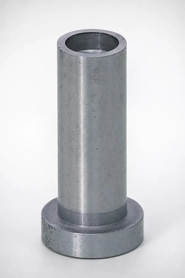
Purge rules are not optional. PVC should not sit above 140 °C in a stationary barrel for more than 10 to 15 minutes, and it must never be left in the tool overnight at temperature. At every planned stop, the machine is purged with ABS or polypropylene, both of which sweep the degraded film off the steel at a lower temperature than the next PVC start allows. Color changes follow the same sequence, and the purge slug is inspected for black specks before the first shot is accepted. A start-up without a purge history is a run of contaminated parts, and the contamination is in the compound, not in the mold.
Regrind discipline closes the loop. Clean PVC sprue and tab scrap is reusable at 10 to 25 percent blend ratios, but any scrap that saw a decomposition event, a black speck or a burnt vent carries carbonized fines that will seed the next thousand shots. Reject that stream, do not dilute it.
PVC Defect Triage: Burns, Bloom and Weld Lines
Burn marks are the signature PVC defect and the first triage question is whether the steel or the process caused them. A burn at a fixed corner that repeats every shot is a missing or blocked vent. A burn that wanders with fill speed is a compressed-air problem from excessive injection velocity. Decomposition burns from an overheated barrel show as black specks distributed through the part, not at one location, and the cure is the screw and the temperature profile, not the vent. The general diagnostic tree is in the burn marks article.
Blooming is a white, waxy haze that appears on the part hours or days after molding. It is excess plasticizer or lubricant migrating out of the compound. Bloom is a material lot problem first, a mold temperature problem second: a cold cavity quenches the surface and pushes low-mass components into the skin. Raise the mold to the upper 30s in Celsius, slow the fill 10 to 15 percent, and quarantine the compound lot.
Weld lines form where two flow fronts meet around a core, and on PVC the bond is weak because the high viscosity front arrives cool. Expect 15 to 30 percent strength loss at an untreated weld on rigid grades. Move the weld to a compressed zone behind a boss, add a vent directly at the meet line, thicken the section locally by 20 to 30 percent, or raise melt and mold temperature within the window. The full method for locating and reinforcing welds is in the weld line reduction guide.
PVC Mold Design FAQ
Q1. What mold temperature does rigid PVC need?
20 to 40 °C at the cavity face, held on both halves within 5 °C of each other. Cooler faces freeze the gate on a high viscosity melt and hotter faces extend an already long cooling time.
Q2. Why can PVC not run a pin gate?
Shear heating across a 0.5 to 1.5 mm restriction adds 10 to 20 °C to a melt already running within 10 °C of its 220 °C decomposition ceiling. The gate carbonizes and plugs the vent. Edge and tab gates at 60 to 100 percent of wall are the standard.
Q3. How deep should PVC vents be?
0.005 to 0.01 mm with a 2 to 3 mm land, then relief to atmosphere. Deeper flashes the low viscosity of the degraded acid film; shallower traps air and burns the last fill corner.
Q4. Which steel stops PVC corrosion?
Hardened 420 stainless for cavities and cores, 416 for machined plates, both plated. Hard chrome at 0.02 to 0.05 mm is the working surface and the sacrificial layer. Plain P20 etches within weeks.
Q5. Can a PVC tool use a hot runner?
Only with a corrosion resistant, dead-spot free unit and residence time logged. Most programs use a chilled cold runner because minutes at melt temperature consumes the stabilizer package.
The Bottom Line
A PVC mold is four numbers and one habit. Keep the melt inside 160 to 210 °C and never above 220 °C. Cut vents at 0.005 to 0.01 mm with a 2 to 3 mm land. Gate at 60 to 100 percent of the wall in edge or tab geometry, never a pin. Run 420 or 416 stainless, plated, polished to Ra under 0.2 micrometre, with cooling at 6 to 10 mm from the face because the resin conducts at 0.14 to 0.17 W per m-K. The habit is purge discipline: no resin sits in a hot barrel overnight. Design to those numbers and a PVC tool runs 500,000 shots with etched but serviceable chrome. Ignore them and you are re-plating inserts in week six while a furnace of hydrochloric acid works on your parting line.
DieStrike builds corrosion-resistant injection molds to IATF 16949 with ±0.005 mm mold accuracy, HRC 62 maximum heat treatment and 120+ machines. Standard components ship in 3 to 7 days and tool lead times run 2 to 5 weeks. Send the resin datasheet and the fitting drawing, and we return a DFM review that flags the gate, vent and steel decisions before the first cut.
KEEP READING
Related Reading
Stainless Mold Steel: 17-4PH vs 420
Where the corrosion resistant stainless grades sit against each other on hardness, polish and price.
Read articleArticleHow to Clean Mold Cooling Channels
Scale, flow loss and the cleaning intervals that keep a heat starved tool on cycle.
Read articleProductMold Heating and Cooling Components
Baffles, bubblers, fittings and rotary joints for dense cooling circuits.
Read articleServiceInjection Mold Manufacturing
IATF 16949 mold building with 2 to 5 week lead times and DFM feedback in 24 hours.
Read articleNEXT STEP
Ready to Start Your Mold?
Send us your element dimensions or part numbers — our team responds within 24 hours with pricing and lead time.

Written by
Ray ChanMold Buyer's Guide Author · Precision Mold Manufacturing Specialist. Ray helps global importers, distributors and OEMs source factory-direct molds and mold parts.